

Transparent substrate which can be used alternatively or cumulatively, for thermal control, for electromagnetic armour and for heated glazing
a transparent substrate and thermal control technology, applied in the field of glazing, can solve the problems of stack not being able to achieve true effective electromagnetic shielding, stack resistivity not being able to achieve much less than 1.8, and stack not being able to achieve resistance per squar
Active Publication Date: 2011-09-29
SAINT-GOBAIN GLASS FRANCE
View PDF8 Cites 19 Cited by
- Summary
- Abstract
- Description
- Claims
- Application Information
AI Technical Summary
Benefits of technology
The invention proposes a substrate with a thin-film stack that can be used for thermal control, electromagnetic shielding, and heating, among others. The substrate has a low resistance per square and can undergo a heat treatment of the bending or toughening type without losing its effectiveness. The stack has a resistance per square that can be modified by changing certain parameters, such as thickness values. The substrate can be made of glass and the layers of the stack can be deposited on top of each other, allowing for easy modification of the production line. The substrate can be used for various applications such as automobile windows, building windows, and electromagnetically shielded glazing. The major advantage of the invention is that it provides a versatile substrate that can be used for multiple applications simultaneously, saving time and resources.
Problems solved by technology
However, within the thickness ranges disclosed, such a stack cannot be used to produce a heated window or electromagnetically shielded window of acceptable appearance (optical characteristics).
However, the resistivity of this stack does not allow true effective electromagnetic shielding to be achieved as its resistance per square R∥ cannot be close to, and a fortiori less than, 1.5 ohms per square.
However, this stack does not make it possible to achieve a resistance per square that is much less than 1.8 ohms per square with optical characteristics (TL, RL, color, etc.) that are deemed to be acceptable, and especially a low light reflection RL in the visible.
Silver-film-based stacks are manufactured in very complex manufacturing units.
The major drawback of the prior art lies in the fact that it is essential to make major modifications to the production line when it is desired to use the production line to manufacture, on the substrate, a thin-film stack that does not have the same application(s) as the stack manufactured previously on this same line.
In general, this operation lasts from several hours to several days, it is tedious and entails a very substantial loss of money, as it is not possible to produce glazing during this transition / adjustment period.
In particular, whenever the material of the target differs from one product to the next, the chamber must be returned to atmospheric pressure before the target is changed, then the chamber must be pumped down to a vacuum (of the order of 10−6 bar), which is obviously time consuming and tedious.
Method used
View moreImage
Smart ImageViewing Examples

Examples
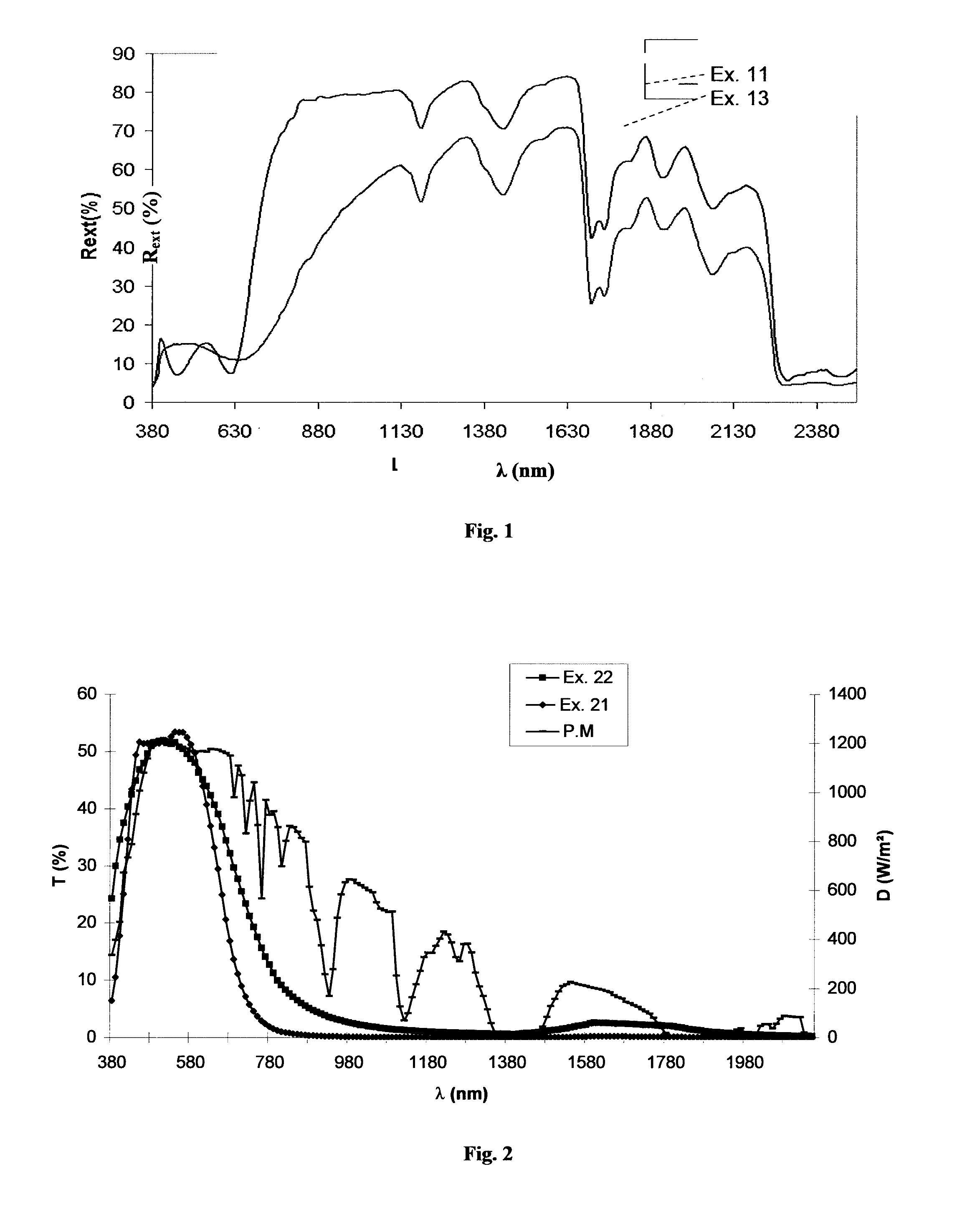
example 11
According to the Invention, Three-Layer
[0103]
LayerSi3N4ZnOAg1ZnOSi3N4ZnOAg2ZnOSi3N4ZnOAg3ZnOSi3N4Thick-37712.5849712.5853712.5829ness(nm)
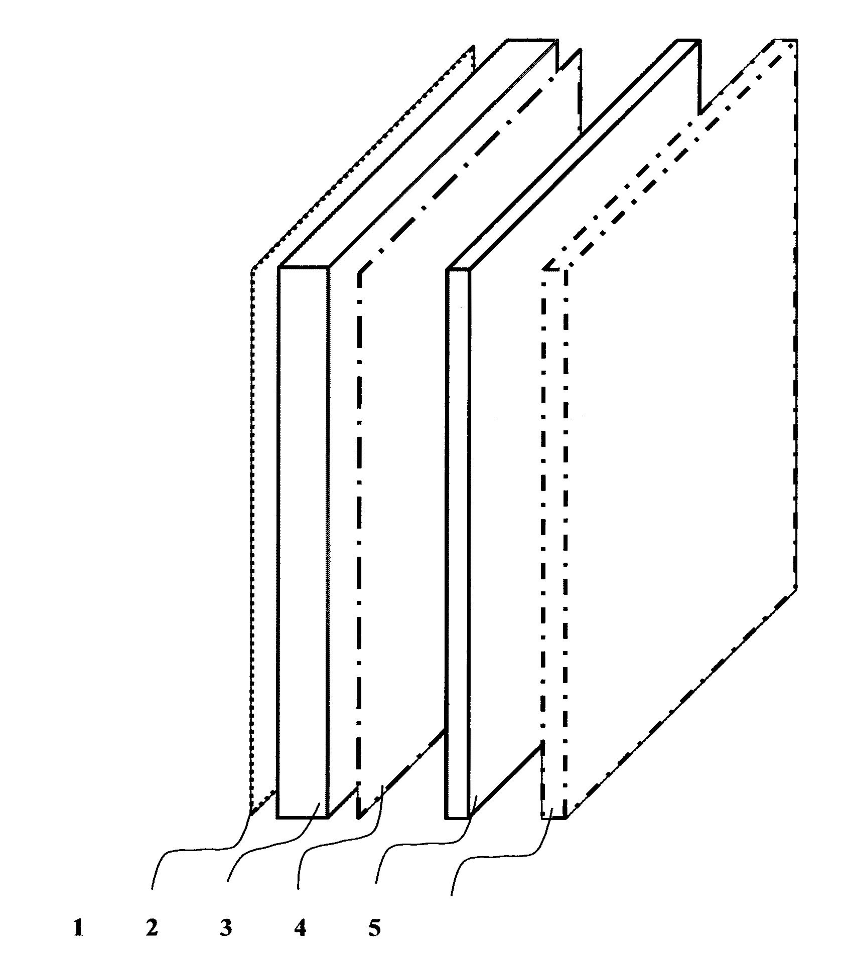
outside / glass (2.1 mm) / PVB (0.76 mm) / Ag3 / Ag2 / Ag1 / glass (1.6 mm) / inside
example 12
According to the Invention, Three-Layer
[0104]Same stack as in Example 11 but also with a titanium overblocker on top of each functional layer (thickness around 0.5 nm to 1 nm).
example 13
Two-Layer Comparative Example
[0105]
LayerSi3N4ZnOAg1ZnOSi3N4ZnOAg2ZnOSi3N4Thick-248867087626ness(nm)
outside / glass (2.1 mm) / PVB (0.76 mm) / Ag3 / Ag2 / Ag1 / glass (1.6 mm) / inside with, in addition, a titanium underblocker beneath each functional layer (thickness around 0.5 nm to 1 nm)
Login to View More PUM
| Property | Measurement | Unit |
|---|---|---|
| total thickness | aaaaa | aaaaa |
| total thickness | aaaaa | aaaaa |
| total thickness | aaaaa | aaaaa |
Abstract
A glazing for thermal control and heating is provided. The glazing includes a transparent substrate including glass and provided with a thin-film stack including a plurality of functional layers. The thin-film stack includes at least three silver-based functional layers. The thin-film stack has a resistance R<1.5Ω per square.
Description
CROSS REFERENCE TO RELATED APPLICATIONS[0001]This application is a continuation application of and claims the benefit of priority under 35 U.S.C. §120 for U.S. Ser. No. 10 / 581,056, filed Dec. 19, 2006, which is a National Stage application of PCT / FR04 / 50614, filed Nov. 24, 2004 and claims benefit of priority under 35 U.S.C. §119 from France 0313966, filed Nov. 28, 2003, the entire contents of each of which are incorporated herein by reference.BACKGROUND OF THE INVENTION[0002]I. Field of the Invention[0003]The present invention relates to the field of glazing that can be used alternatively or cumulatively in three particular applications, namely thermal control (solar control and thermal insulation), electromagnetic shielding and heated windows, while still preferably being able to undergo at least one transformation operation involving a heat treatment at a temperature of at least 500° C. (this may be in particular a toughening, annealing or bending operation).[0004]Thermal control ...
Claims
Login to View More Application Information
Patent Timeline
 Patent Type & AuthorityApplications(United States)
IPC IPC(8): B32B17/06B32B15/04B32B9/04B32B7/02B32B17/10C03C17/36
CPCB32B17/10018Y10T428/12576B32B17/10174B32B17/10761B32B2367/00C03C17/36C03C17/3618C03C17/3626C03C17/3639C03C17/3644C03C17/3652C03C17/366C03C17/3673C03C17/3676C03C17/3681H01J2211/446B32B17/10229Y10T428/12611Y10T428/24975Y10T428/12778Y10T428/2495Y10T428/265B32B17/10036C03C17/34
InventorFLEURY, CARINNENADAUD, NICOLASBELLIOT, SYLVAIN
OwnerSAINT-GOBAIN GLASS FRANCE