Suction unit and autonomous vacuum cleaner

a vacuum cleaner and suction unit technology, applied in the direction of vacuum cleaners, mechanical suction control, cleaning equipment, etc., can solve the problems of increasing the normal force acting on the nozzle, increasing the underpressure in the interior space,

Active Publication Date: 2011-10-06
VERSUNI HLDG BV
View PDF7 Cites 15 Cited by
  • Summary
  • Abstract
  • Description
  • Claims
  • Application Information

AI Technical Summary

Benefits of technology

[0004]It is an object of the present invention to provide a suction unit that reduces the abovementioned disadvantage.
[0007]Any enhanced downward force on the nozzle due to increasing pressure therein can effectively be reduced in this manner, while driving the suction unit gets easier. An additional advantage is that the force exerted by the coupling means results in improved traction force of the driving system on the surface to be treated, as the force exerted by the coupling means will be transferred so as to increase the downward force acting on the chassis. This will be explained in more detail below.
[0008]According to a preferred embodiment, the coupling means comprises a bellows interposed between the chassis and the nozzle, the bellows having an interior space that communicates with the interior space of the nozzle. This provides a simple and effective construction for the coupling means. When the underpressure in the nozzle increases, the underpressure in the bellows will increase also. Or, in other words, the pressure in the bellows drops. Accordingly, the bellows will contract and exert a counterforce on the nozzle that is directed away from the surface to be treated. A larger underpressure in the nozzle results in a larger underpressure in the bellows and hence in a larger force that is exerted on the nozzle.
[0010]According to another preferred embodiment, the coupling means comprises a linear actuator interposed between the chassis and the nozzle for moving the nozzle with relation to the chassis in a substantially vertical direction. It is especially preferred that a pressure sensor is provided in the interior space, the sensor giving an output signal, the linear actuator being configured to move the nozzle depending on the output signal of the pressure sensor. This has the advantage that the force that is exerted on the nozzle can be applied in an active manner, which results in a precise control of the forces acting on the nozzle.
[0012]According to another preferred embodiment, the drive system comprises a set of wheels provided at opposite sides of the chassis, wherein the wheels on either side of the chassis can be separately operated. This allows easy turning of the suction unit by driving the wheels at one side of the chassis only.
[0014]The present invention can in particular be advantageously used for the arrangement as described in WO 02 / 074150. This document discloses an autonomous cleaner having a self-propelling moving suction unit or cleaning head that is connected to a main module or vacuum fan module that is also self-propelling and holds a dust container and a fan unit as well as the larger part of the cleaner's navigation and control system. Because the size of the suction unit is relatively small, at least compared to the main module, the maximum power of the drive system therein will be relatively small. Since the suction power generated in the main module typically will be comparable to that of conventional vacuum cleaners, there is an enhanced risk of the suction unit getting stuck to the floor. The maximum power of the drive system then can be insufficient to overcome this. Moreover, the weight of such a suction unit will be relatively low. Accordingly, the normal force acting on the wheels is relatively low, which leads to an enhanced risk of spinning wheels.

Problems solved by technology

If the nozzle gets stuck, the underpressure in the interior space will increase due to the opening being sealed from the environment.
This results in an increased normal force acting on the nozzle.

Method used


Image

  • Suction unit and autonomous vacuum cleaner
  • Suction unit and autonomous vacuum cleaner
  • Suction unit and autonomous vacuum cleaner

Examples


Embodiment Construction

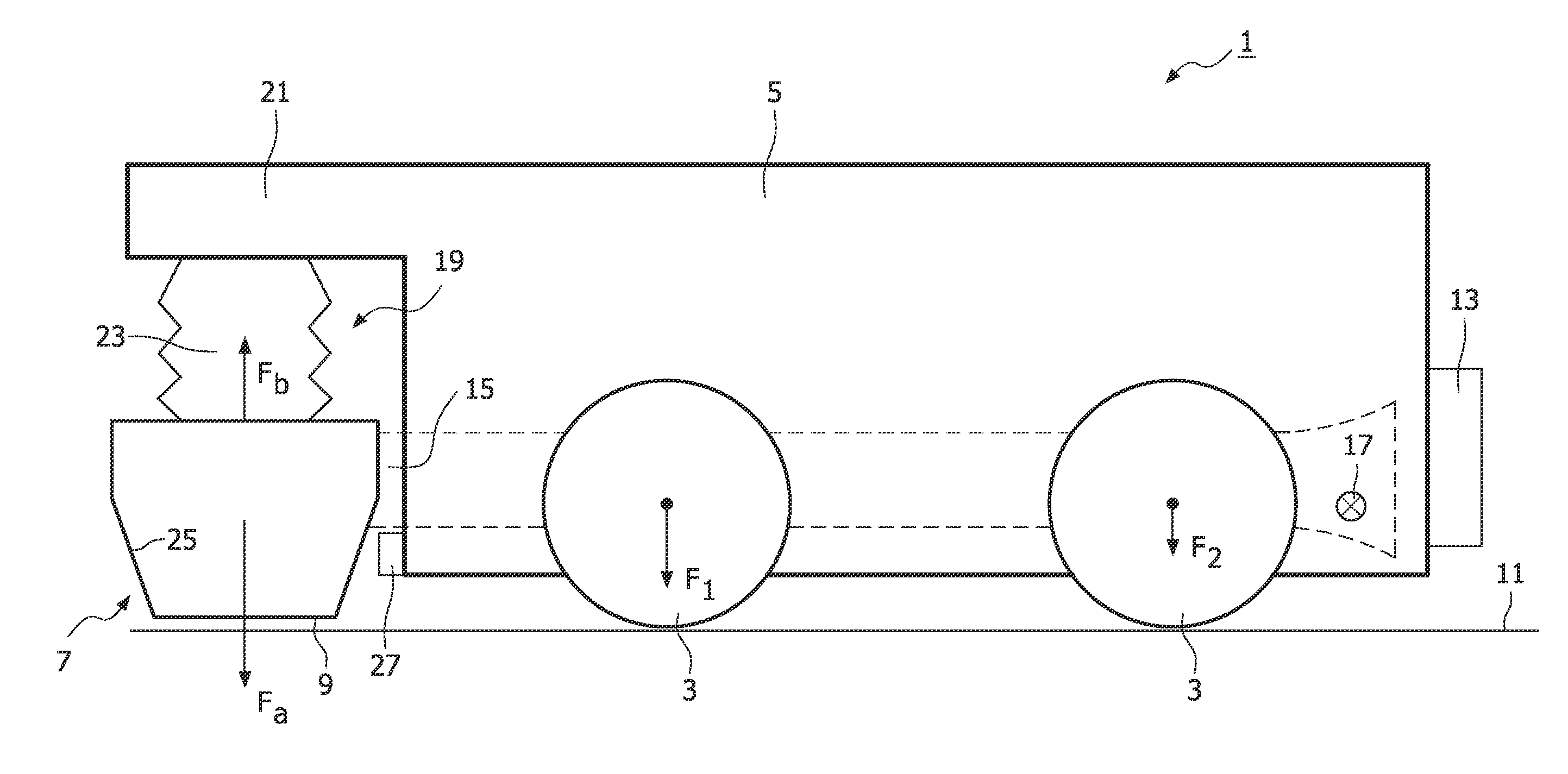
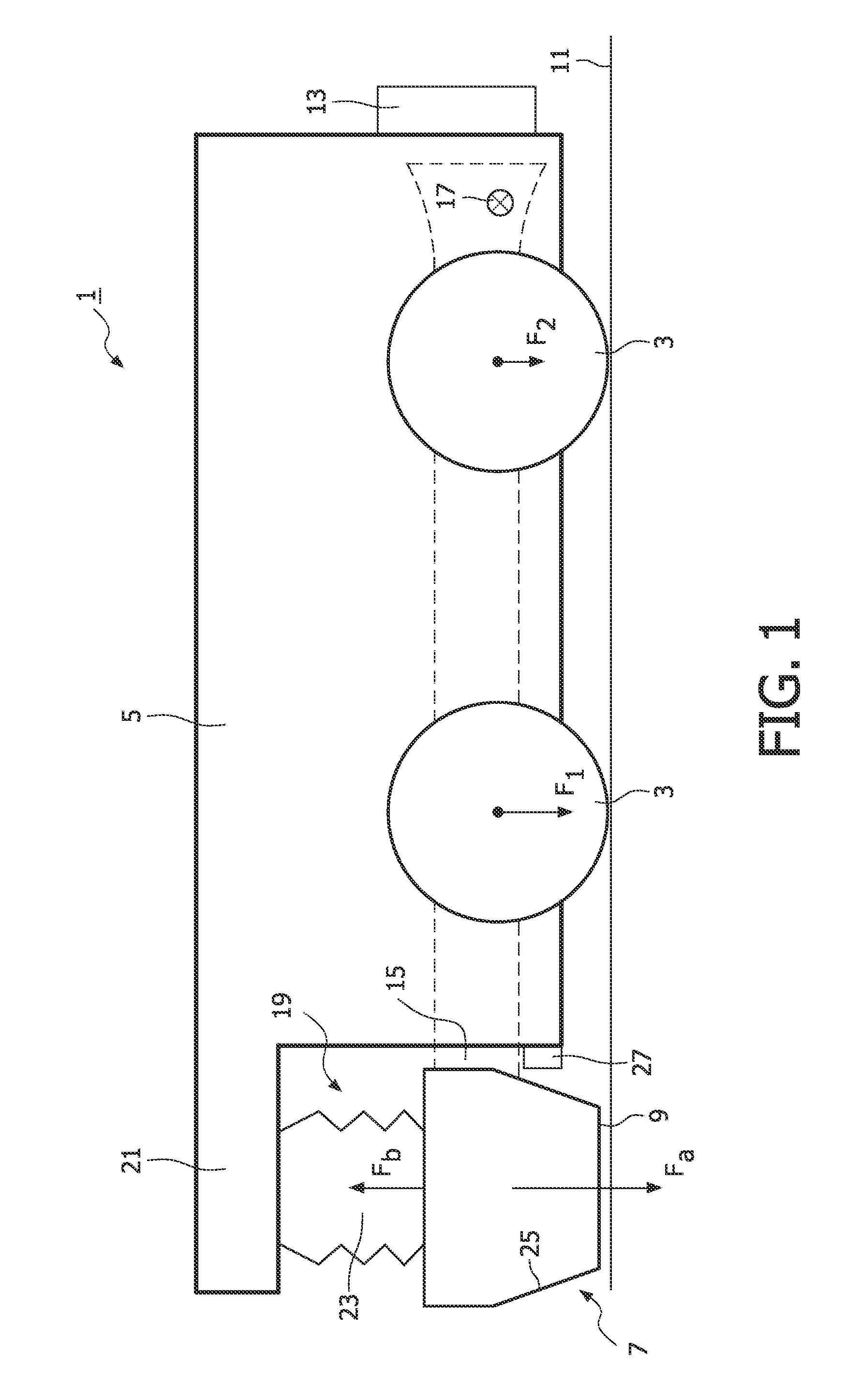
[0020]FIG. 1 shows a suction unit 1 according to a preferred embodiment of the present invention. The suction unit has a drive system that comprises wheels. In this embodiment two sets of wheels 3 are provided on each side. The wheels on either side can be separately operated in order to turn the suction unit. Two electromotors, one on each side, are provided to drive the wheels. Preferable each wheel on the chassis is driven by the motor. Preferably a set of gears (not shown) are interposed between the wheels and an electromotor. The wheels are carried by a chassis 5. Several other parts are also mounted to the chassis.

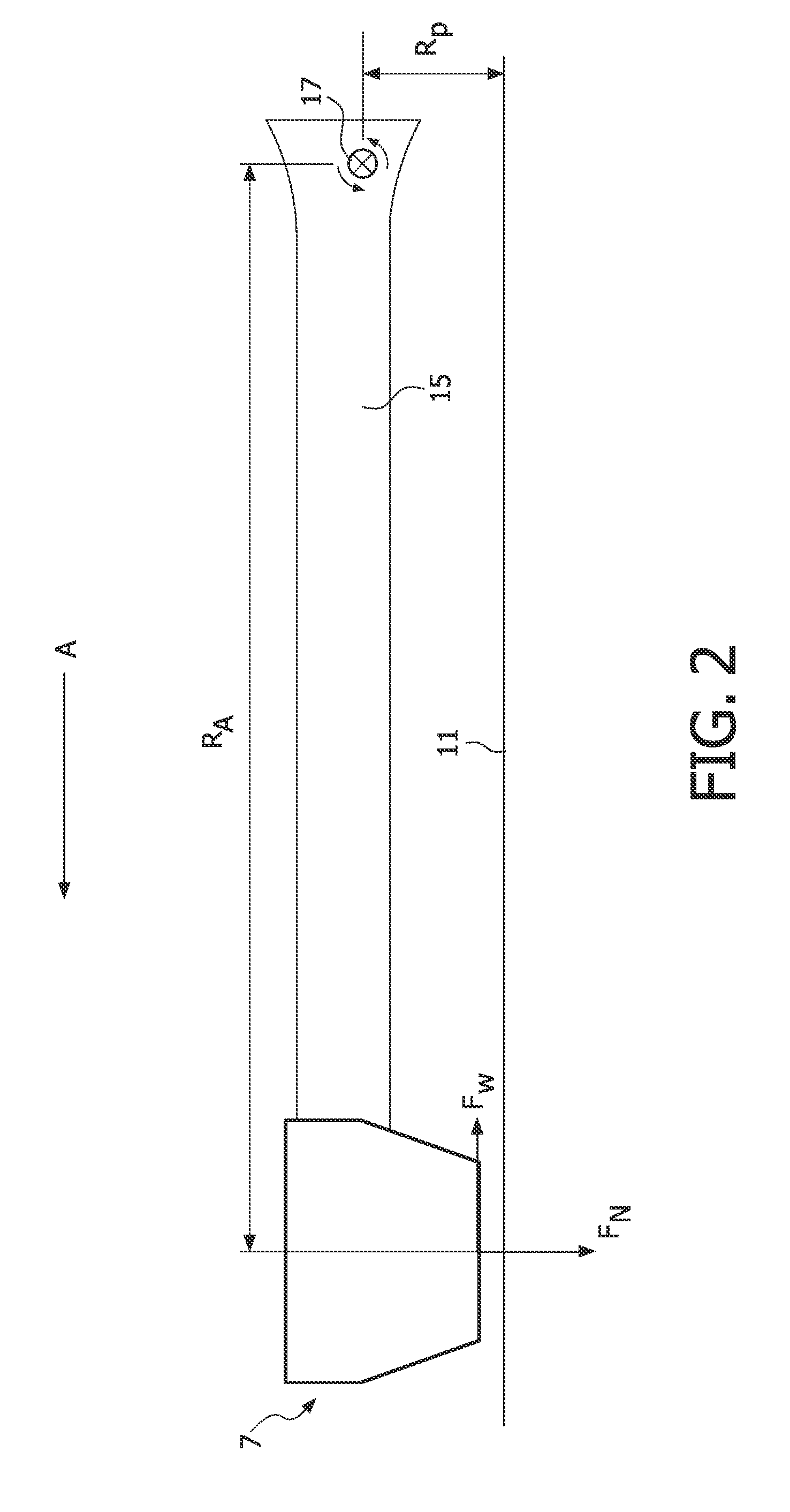
[0021]At a front part of the chassis a nozzle 7 is provided. The nozzle has an interior space defining an opening 9 facing the surface to be treated 11 when the suction unit is operational. The interior space communicates with an outlet 13, while at another side it results in the opening 9. The outlet 13 is meant to communicate with suction means or a fan unit when t...


PUM


Abstract

The invention relates to a suction unit and a vacuum cleaner. The suction unit comprises a drive system for driving the suction unit on a surface to be treated; a chassis supporting the drive system; a nozzle for removing particles from a surface to be treated, which nozzle is configured to move with relation to the chassis in a direction away from the surface to be treated, the nozzle having an interior space defining an opening that faces the surface to be treated; and an outlet communicating with the interior space, the outlet being arranged for communication with a fan unit during operating conditions. The suction unit further comprises coupling means for coupling the nozzle to the chassis, wherein the coupling means is arranged to exert a force that is directed away from the surface to be treated when the underpressure in the interior space increases. In this manner the problem of the suction unit getting stuck on the floor can be overcome or at least reduced. Furthermore, the traction of the drive system can be improved. An autonomous vacuum cleaner according to the invention comprises such a suction unit and further comprises a dust chamber, and a fan unit that communicates with the dust chamber. The fan unit communicates with the outlet for creating an underpressure in the interior space of the nozzle during operating conditions.

Description

FIELD OF THE INVENTION[0001]The present invention relates to a suction unit for an autonomous vacuum cleaner. Furthermore, the invention relates to an autonomous vacuum cleaner.BACKGROUND OF THE INVENTION[0002]In EP0803224 a suction unit is integrated with a fan unit and a dust chamber, and all components are accommodated in the same housing. In EP0803224 the outlet of the nozzle for removing particles from a surface to be treated communicates with a chamber accommodating a dust container. The chamber is connected to a fan unit that provides an underpressure. The nozzle is mounted to the chassis by an arm that is supported by a ball joint so that it can pivot with relation to the housing. During movement of the vacuum cleaner across the floor, the nozzle rests by its own weight on the floor and floats on the floor because of the flexible support at the ball joint.[0003]A problem with known suction units is that when the nozzle is completely sealed from the outside atmosphere, the un...

Claims


Application Information

Patent Timeline
Patent Type & Authority Applications(United States)
IPC IPC(8): A47L9/02A47L9/28A47L5/00
CPCA47L9/0072A47L9/009A47L2201/00A47L9/2821A47L9/02A47L5/04
Inventor DEKKERS, JEROENRUIJL, THEO ANJES MARIAREIJNDERS, SILVESTER MATHEUSVAN EIJK, JANVROOMEN, HUBERT GERARD JEAN JOSEPH AMAURYWARMERDAM, THOMAS PETRUS HENDRICUSRIJS, ROBERTUS MATHIJS GERARDUS
Owner VERSUNI HLDG BV
Why Eureka
Try Eureka