
Triaxial vibration composite testing apparatus

a triaxial vibration and composite testing technology, applied in the direction of vibration testing, structural/machine measurement, mechanical vibration separation, etc., can solve the problems of increasing manufacturing costs, affecting the vibration frequency response characteristic, and poor vibration response characteristic in the perpendicular z axial direction, so as to increase the rigidity. the effect of the whol

Active Publication Date: 2011-10-06
SUZHOU SUSHI TESTING INSTR CO LTD
View PDF7 Cites 22 Cited by
  • Summary
  • Abstract
  • Description
  • Claims
  • Application Information

AI Technical Summary

Benefits of technology

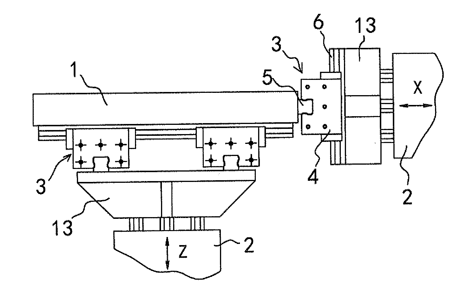
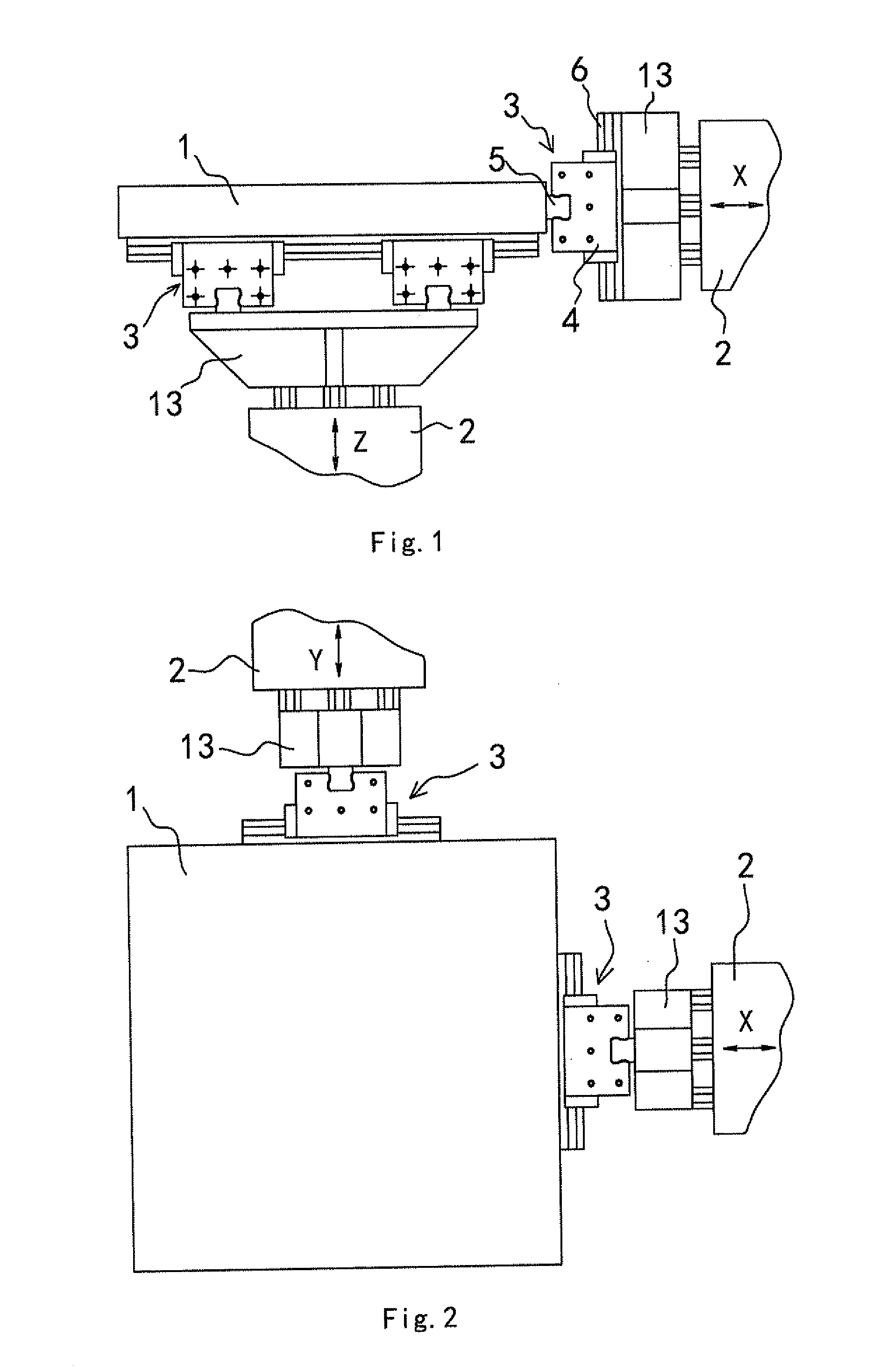
[0027]1. With the special structure of the present invention, since the axial vibration transmission mechanism in the X axial and the Y axial directions is changed into the cross linear guide pair, the working tabletop does not need to be provided on the side with a pressure application plate, which can shorten as far as possible the distance between the working tabletop and the Z axial vibration generator in the perpendicular Z axial direction (i.e. lowering the working tabletop), thus increasing the entire rigidity.
[0028]2. With the special structure of the present invention, since the axial vibration transmission mechanism in the X axial and the Y axial directions is changed into the cross linear guide pair, the working tabletop does not need to be provided on the side with a pressure application plate, which reduces the number of the middle cubes as well as the mass of the motion part in the triaxial directions.
[0029]3. The present invention is increased in rigidity and decreased in mass of the motion part, which further increases the upper working frequency limit.
[0030]4. With the special structure of the present invention, since the axial vibration transmission mechanism in the X axial and the Y axial directions is changed into the cross linear guide pair, the working tabletop is lowered, thus improving the antioverturning moment capacity.
[0031]5. The cross linear guide pair of the present invention can be bought, which simplifies the mechanical structure, lowers the manufacturing difficulty, and greatly reduces the manufacturing cost.

Problems solved by technology

2) There are so many connection joints on the force transmission path from the vibration generator 2 to the working tabletop 1 that the vibration frequency response characteristic is affected, and especially its vibration response characteristic in the perpendicular Z axial direction is very poor, which makes it applicable to the low frequency vibration test.
Because of the hydrostatic bearing structure in all the triaxial directions, the structure is more complicated, and each of the fit planes is high in requirement and hard to be processed, which increases the manufacturing cost.

Method used


Image

  • Triaxial vibration composite testing apparatus
  • Triaxial vibration composite testing apparatus
  • Triaxial vibration composite testing apparatus

Examples


embodiment 1

[0042] As shown in FIGS. 4 to 5, a triaxial vibration composite testing apparatus is provided including a working tabletop 20, which is connected in a perpendicular Z axial direction with a Z axial vibration generator 21 through a first axial vibration transmission mechanism 24, in a horizontal X axial direction with an X axial vibration generator 22 through a second axial vibration transmission mechanism 25, and in a horizontal Y axial direction with a Y axial vibration generator 23 through a third axial vibration transmission mechanism 26.

[0043]The first axial vibration transmission mechanism 24 includes an upper clamp 27 and a lower clamp 28 and a central panel 29. The working tabletop 20 is provided below with a connection body 41. The connection body 41, having an H-shaped cross section, is in fixed connection at its top circumferential wall with the bottom of the working tabletop 20, with its central transverse plate being the central panel 29. The upper clamp 27 and the lower...


PUM


Abstract

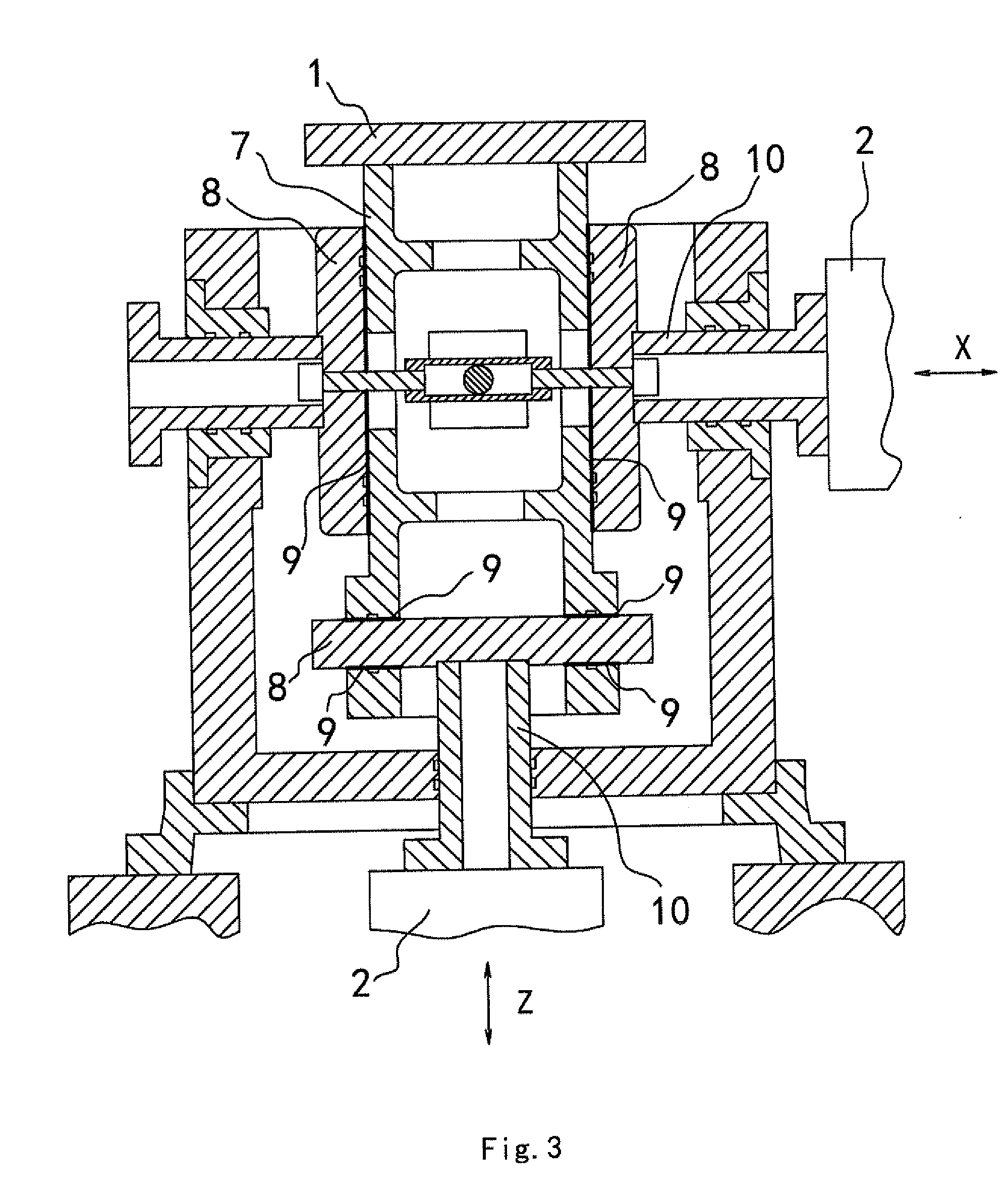
A triaxial vibration composite testing apparatus including a working tabletop, wherein the second axial vibration transmission mechanism in the horizontal X axial direction and the third axial vibration transmission mechanism in the horizontal Y axial direction are both cross linear guide pairs; the first axial vibration transmission mechanism in the perpendicular Z axial direction includes an upper and a lower clamps and a central panel, the upper and the lower clamps being horizontally opposite to each other up and down, the central panel being positioned between the upper and the lower clamps, the upper and the lower clamps oppositely clamping the central panel; a gap fit between the lower surface of the upper clamp and the upper surface of the central panel forms an upper fit plane, and a gap fit between the upper surface of the lower clamp and the lower surface of the central panel a lower fit plane; and the high pressure oil is pumped into the upper fit plane gap and the lower fit plane gap to form a hydrostatic oil film, thus constituting a hydrostatic plane bearing mechanism.

Description

[0001]This is a Continuation of International Application No. PCT / CN2009 / 000372 filed Apr. 3, 2009, which claims the benefit of Chinese Patent Application No. 200910024507.X filed Feb. 13, 2009. The disclosure of the prior applications is hereby incorporated by reference herein in its entirety.FIELD OF THE INVENTION[0002]The present invention relates to a mechanical condition testing device, and particularly to an X-Y-Z triaxial vibration composite testing apparatus. This triaxial vibration composite testing apparatus can be used for simulating both the separate vibration condition and the composite vibration condition simultaneously in the X, Y and Z axial directions.BACKGROUND OF THE INVENTION[0003]The natural vibration a product experiences under the actual working condition is the composite vibration in the triaxial directions of X, Y and Z. In order to actually show the vibration resistance of the product and simulate the natural vibration condition, a triaxial vibration compos...

Claims


Application Information

Patent Timeline
IPC IPC(8): B06B3/00
CPCG01M7/06
Inventor WU, YUANZHENZHONG, QIONGHUA
Owner SUZHOU SUSHI TESTING INSTR CO LTD
Learn More