Cord for reinforcement of a cementitious matrix

a cementitious matrix and cord technology, applied in the direction of yarn, textiles and papermaking, building components, etc., can solve the problems of galvanized steel elements, aesthetic problems, strength and durability problems, etc., and achieve the effect of preventing the evolution of hydrogen gas

Inactive Publication Date: 2011-10-06
NV BEKAERT SA
View PDF11 Cites 2 Cited by
  • Summary
  • Abstract
  • Description
  • Claims
  • Application Information

AI Technical Summary

Benefits of technology

[0084]It is a great advantage of the present invention that hydrogen gas evolution is also prevented in case cement free of hexavalent chromium is used and in case cement is dosed with ferrous sulphate.
[0085]The reinforced cementitious matrix can be used for any application known in the art such as prefabrication constructions, bridges, buildings, tunnels, parking garages, offshore oil platform, . . . .
[0086]For the purpose of this invention, “cementitious matrix” should be understood to mean the matrix material apart from the metal elements. The cementitious matrix may comprise any material comprising cement as for example concrete or mortar.
[0087]According to a further aspect of the present invention a method for inhibiting hydrogen gas evolution at the interface of a cord comprising coated filaments embedded in a cementitious matrix is provided. The method comprises the steps of providing at least one cord as described above, introducing said cord in a cementitious matrix.
[0088]The description will now be described into more detail with reference to the accompanying drawings wherein
[0089]FIG. 1, FIG. 2 and FIG. 3 show cross-sections of cords according to the present invention;

Problems solved by technology

However, the use of galvanized steel elements in concrete is creating problems: during hardening of the concrete, the galvanized surface of the steel elements will react with the alkaline environment of the concrete to form zinc salts accompanied by hydrogen gas evolution.
Hydrogen gas evolution leads to strength and durability problems, as well as to aesthetical problems.
This is resulting in a reduction of the strength of the reinforced concrete.
The durability problem is the result of the reduction in the thickness of the alloy coating due to the reaction of the alloy coating in the alkaline environment.
However, in recent years it has been recognized that hexavalent chromium raises serious environmental and health problems.
However, epoxy coatings have serious drawbacks as epoxy coatings act a barrier against a corrosive environment.
If there are defects in the epoxy coating through which aggressive agents can penetrate the barrier, corrosion will concentrate on these areas.
Local corrosion could make the steel element break where the coating is damaged.
Epoxy coatings are fragile.
Consequently, as the mixing or installation of the reinforcement elements in the concrete is a rough operation whereby local damages on the surface of reinforcement elements are unavoidable, the use of epoxy coated metal elements or other compounds applied at the surface for the reinforcement of concrete is not a good option.
However, these inhibitors did not give an adequate result as they were not able to avoid hydrogen gas evolution.
Not only is the process for applying a sufficient amount of compound to the surface of e.g. a zinc coated metal element industrially very difficult, said elements must also be handled with a lot of care during storing, transport and handling to prevent damage to the surface.

Method used


Image

  • Cord for reinforcement of a cementitious matrix
  • Cord for reinforcement of a cementitious matrix
  • Cord for reinforcement of a cementitious matrix

Examples


example 1

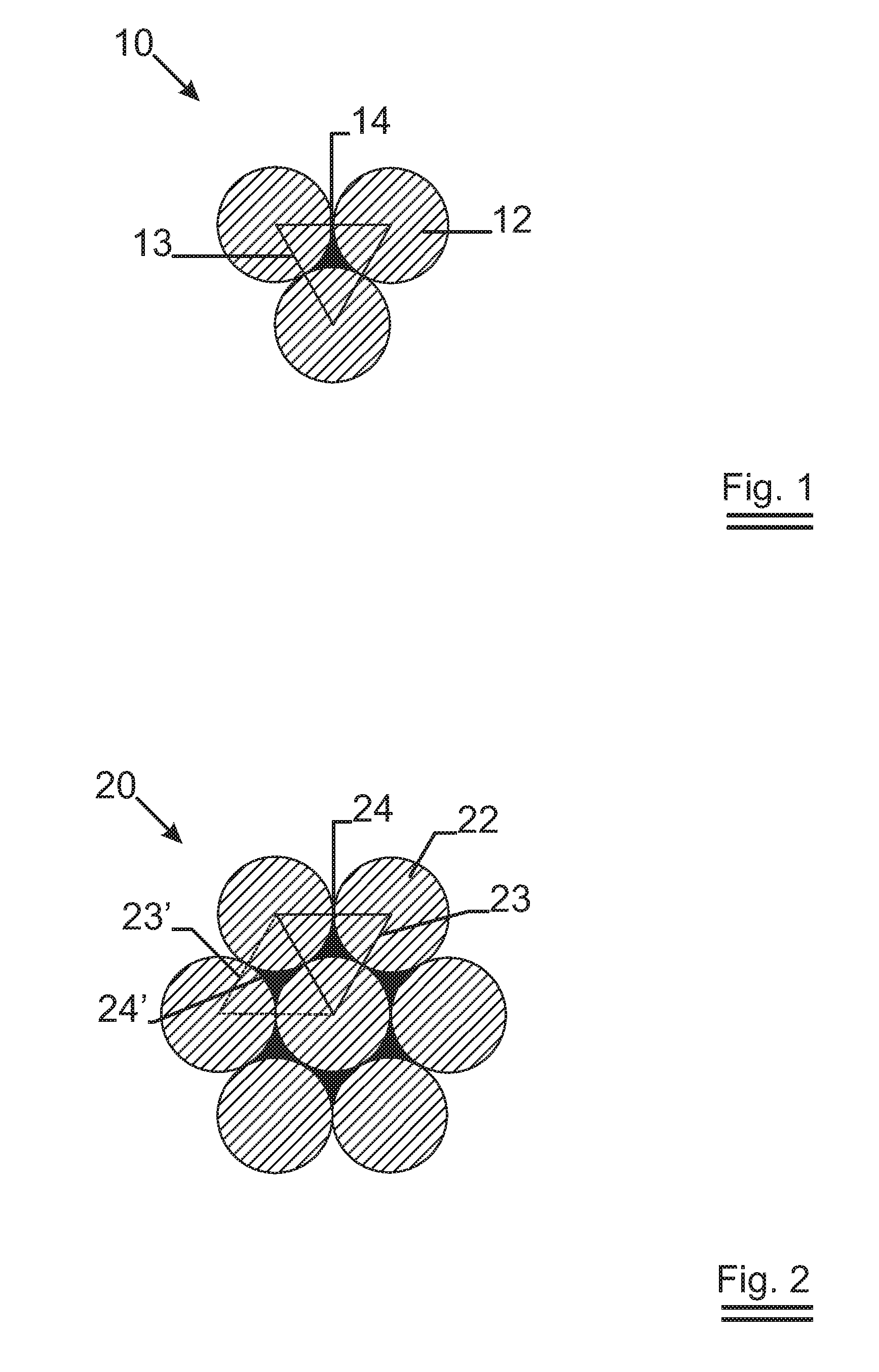
[0092]FIG. 1 shows a cross-section of a cord 10 for the reinforcement of a cementitious matrix according to the present invention. The cord 10 comprises three zinc coated metal filaments 12 twisted together. The three filaments form a closed sub-structure 13 whereby neighbouring filaments 12 of the closed sub-structure 13 are maximum 30 μm remote from each other. A void 14 is hereby formed in the middle of the three filaments 12 of the closed sub-structure 13. A protective compound, as for example benzimidazole is present in said void. Possibly, the protective compound is also present on at least a part of the zinc coated metal filaments 12.

example 2

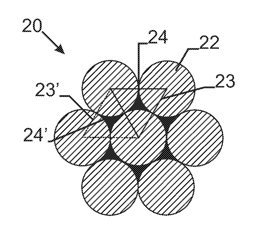
[0093]FIG. 2 shows a cross-section of a cord 20 for the reinforcement of a cementitious matrix according to the present invention. The cord 20 comprises 7 filaments 22. Neighbouring filaments form closed sub-structures 23, 23′. Neighbouring filaments 22 of a closes-substructure are maximum 100 μm remote form each other. Voids 24, 24′ are formed in the middle of filaments of a closed substructure 23, 23′. A protective compound is present in the voids 24, 24′ of the closed substructures 23. Possibly, the protective compound is also present on at least a part of the zinc coated metal filaments 22.

example 3

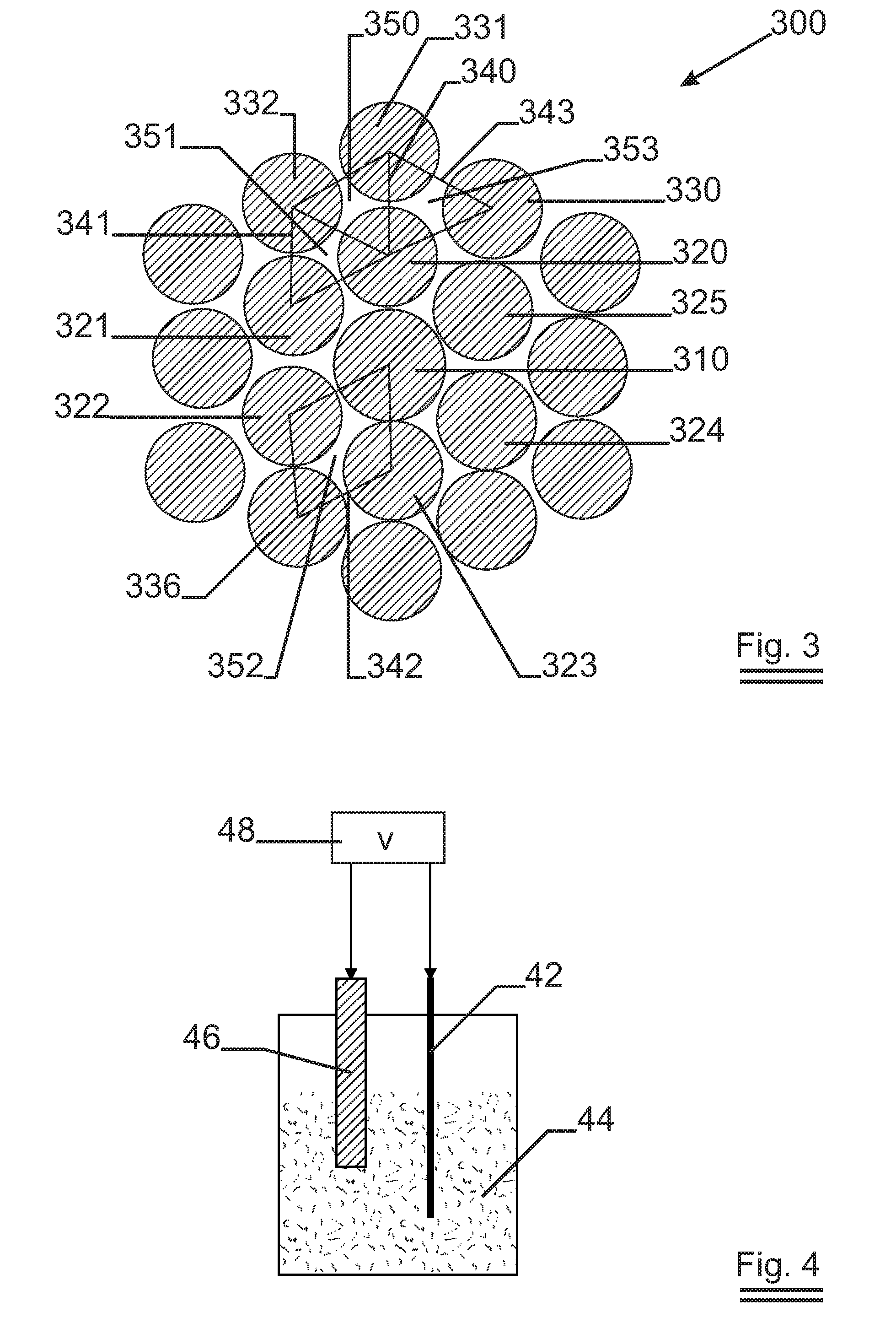
[0094]FIG. 3 shows a cross-section of a brass coated compact cord 300 having a 0.34+18×0.30 construction. Around the central somewhat thicker filament 310 of 0.34 mm diameter, 18 filaments of diameter 0.30 have been cabled in one operation with a lay length of 21 mm in the Z direction. The cable has many voids. The filaments 320, 331 and 332 form a closed sub-structure 340 having a void 350 as the neighbouring filaments 320, 331 and 332 are less than 30 μm remote form each other. Similarly the filaments 320, 321 and 332 form a closed sub-structure 341 having a void 351 as the neighbouring filaments 320, 321 and 332 are less than 30 μm remote from each other. Also the filaments 310, 322, 336 and 323 form a closed substructure 342 having a void 352 as the neighbouring filaments 310, 322, 336 and 323 are less than 30 μm remote from each other. On the other hand the filaments 320, 330, 331 does not form a closed sub-structure as the filaments 330 and 331 are more than 100 μm remote from...


PUM

PropertyMeasurementUnit
wt %aaaaaaaaaa
wt %aaaaaaaaaa
lay lengthaaaaaaaaaa

Abstract

The invention relates a cord for the reinforcement of a cementitious matrix. The cord comprises number of coated metal filaments twisted together to form a cord. The cord shows cross-sections, whereby three or more of the filaments form a closed sub-structure having a void in the middle of the three or more filaments. The cord further comprises a protective compound whereby the protective compound is at least present in said void. The protective compound gives the coated metal element cathodic protection. The invention further relates to a structure comprising a number of cords such as a knitted, a braided, a welded or a glued structure. Furthermore the invention relates to a cementitious matrix reinforced with a cord according to the present invention and to a method to inhibit hydrogen gas evolution at the interface of a cord embedded in a cementitious matrix.

Description

TECHNICAL FIELD[0001]The invention relates to a cord for reinforcement of a cementitious matrix having a protective compound present at least in the voids of the cord and to a structure comprising a number of such cords.[0002]The invention further relates to a reinforced cementitious matrix comprising at least such a cord. Furthermore, the invention relates to a method for inhibiting hydrogen gas evolution.BACKGROUND ART[0003]It is generally known to reinforce concrete structures with metal elements, such as steel fibers, to give the structures the required mechanical properties.[0004]As bare steel elements may suffer from corrosion, galvanized steel elements have been proposed to give the steel elements a long term corrosion resistance. Galvanized reinforcing steel elements are especially useful for the reinforcement of concrete for construction purposes whereby the reinforced concrete will be exposed to the weather before construction begins, as for example in prefabrication const...

Claims


Application Information

Patent Timeline
Patent Type & Authority Applications(United States)
IPC IPC(8): C04B14/48D02G3/02
CPCD07B1/0693D07B1/144E04C5/08D07B2501/2023E04C5/015D07B2401/2025
Inventor DE SMET, ANNELEENVANBRABANT, JAHAN
Owner NV BEKAERT SA
Why Eureka
Try Eureka