Variable capacitor and position indicator
a capacitor and position indicator technology, applied in the direction of resistance/reactance/impedence, instruments, measurement devices, etc., can solve the problem of not artificially achieved
- Summary
- Abstract
- Description
- Claims
- Application Information
AI Technical Summary
Benefits of technology
Problems solved by technology
Method used
Image
Examples
second embodiment
[Variable Capacitor of the Second Embodiment]
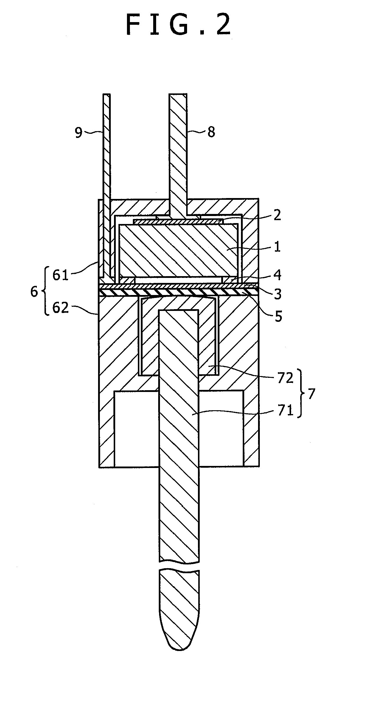
[0123]Next, description will be given with respect to the variable capacitor of a second embodiment of the present invention. The variable capacitor of the second embodiment is realized by the following technique used in the variable capacitor disclosed in Patent Document 3 described above, and by further improving that technique. It is to be noted that for the sake of simplifying the description, in the variable capacitor of the second embodiment, portions which are formed similarly to those in the variable capacitor of the first embodiment described with reference to FIG. 2 to FIGS. 10A to 10E are designated by the same reference numerals, respectively, and a detailed description thereof is omitted.
[0124]FIG. 12 is a cross sectional view showing a construction of the variable capacitor of the second embodiment. As can be seen by comparing the cross sectional view of FIG. 12 with the cross sectional view showing the construction of the v...
third embodiment
[Variable Capacitor of the Third Embodiment]
[0143]Next, description will be given with respect to the variable capacitor of a third embodiment of the present invention. The variable capacitor of the third embodiment is realized by following the technique used in the variable capacitor disclosed in the previous application (Japanese Patent Application No. 2008-305556) described above, and by further improving that technique.
[0144]FIG. 15 is a perspective view of the variable capacitor of the third embodiment, and FIG. 16 is a cross sectional view taken along line B-B′ of the variable capacitor shown in FIG. 15. The variable capacitor of the third embodiment also changes its capacitance value in accordance with the pressure applied thereto similarly to the case of each of the variable capacitor of the first and second embodiments described above.
[0145]Inside of a housing 121 of the variable capacitor of the third embodiment has a hollow approximately cylindrical shape. The inside of t...
fourth embodiment
[Variable Capacitor of the Fourth Embodiment]
[0175]Next, description will be given with respect to the variable capacitor of a fourth embodiment of the present invention. The variable capacitor of the fourth embodiment is constructed approximately similarly to the case of the variable capacitor of the third embodiment described with reference to FIG. 15 to FIGS. 18A to 18C. That is, the variable capacitor of the fourth embodiment is constructed similarly to the case of the variable capacitor of the third embodiment except that construction of the dielectric 122 and the conductive member 126 forming the second electrode is different from that in the variable capacitor of the third embodiment. Other than these parts, the variable capacitor of the fourth embodiment is configured similarly to that of the third embodiment.
[0176]For this reason, since the variable capacitor of the fourth embodiment is constructed approximately similarly to the case of the variable capacitor of the third e...
PUM
 Abstract
Description
Claims
Application Information
 - R&D
- Intellectual Property
- Life Sciences
- Materials
- Tech Scout
- Unparalleled Data Quality
- Higher Quality Content
- 60% Fewer Hallucinations
Browse by: Latest US Patents, China's latest patents, Technical Efficacy Thesaurus, Application Domain, Technology Topic, Popular Technical Reports.
© 2025 PatSnap. All rights reserved.Legal|Privacy policy|Modern Slavery Act Transparency Statement|Sitemap|About US| Contact US: help@patsnap.com


