Self-powered, piezo-surface acoustic wave apparatus and method

a piezoelectric surface and acoustic wave technology, applied in the field of self-powered piezoelectric surface acoustic wave transducers, can solve the problems of limiting the size reduction of devices for certain applications, short useful life of conventional batteries, and inability to operate well or at all at high or low temperatures

Active Publication Date: 2011-10-06
CORNELL UNIVERSITY
View PDF12 Cites 23 Cited by
  • Summary
  • Abstract
  • Description
  • Claims
  • Application Information

AI Technical Summary

Problems solved by technology

Even the smallest conventional batteries may be much larger than the MEMS for which they are supplying power, thus limiting the size reduction of devices for certain applications.
In addition, conventional batteries have relatively short useful lifetimes, often on the order of days to, at most, several months, and may not operate well or at all at high or low temperatures.

Method used


Image

  • Self-powered, piezo-surface acoustic wave apparatus and method
  • Self-powered, piezo-surface acoustic wave apparatus and method
  • Self-powered, piezo-surface acoustic wave apparatus and method

Examples


Embodiment Construction

[0037]Reference will now be made in detail to the present exemplary embodiments of the invention, examples of which are illustrated in the accompanying drawings. Wherever possible, the same reference numbers will be used throughout the drawings to refer to the same or like parts.

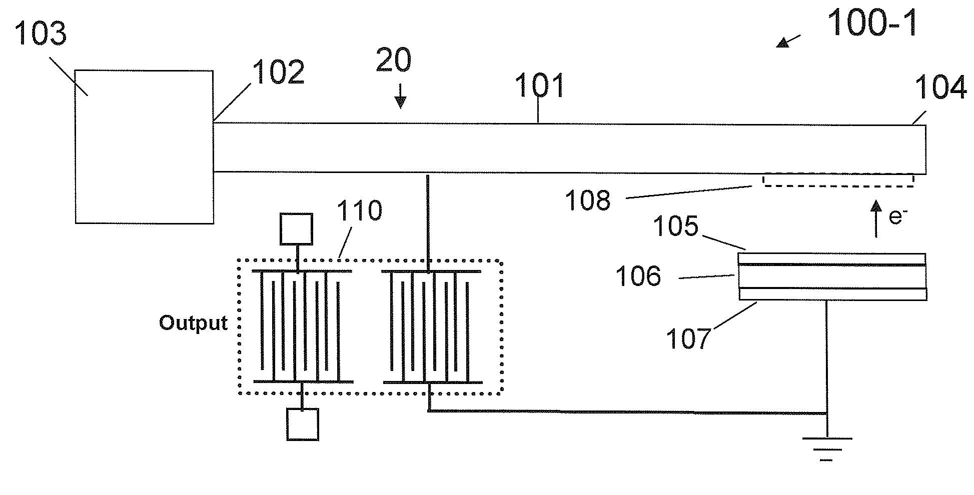
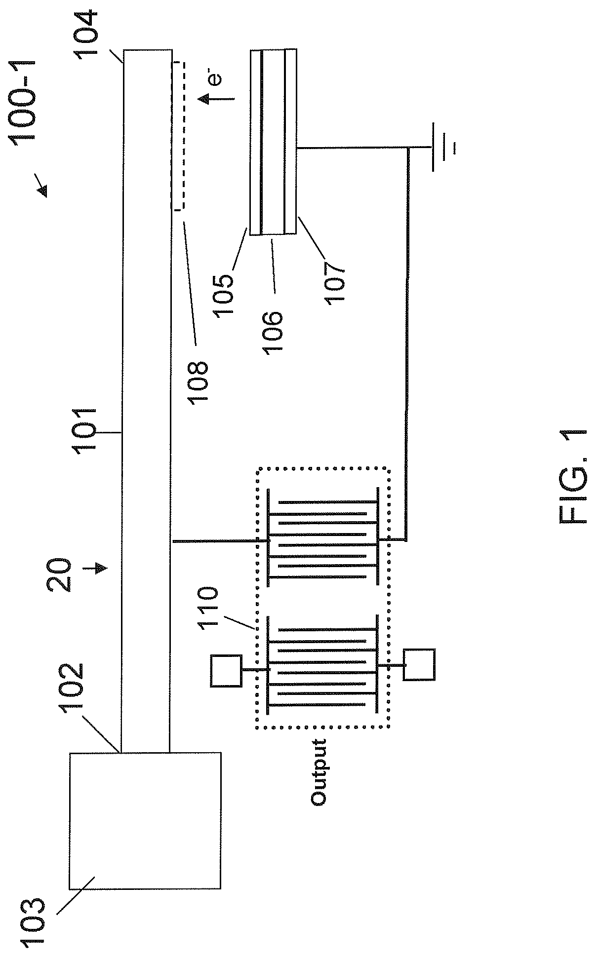
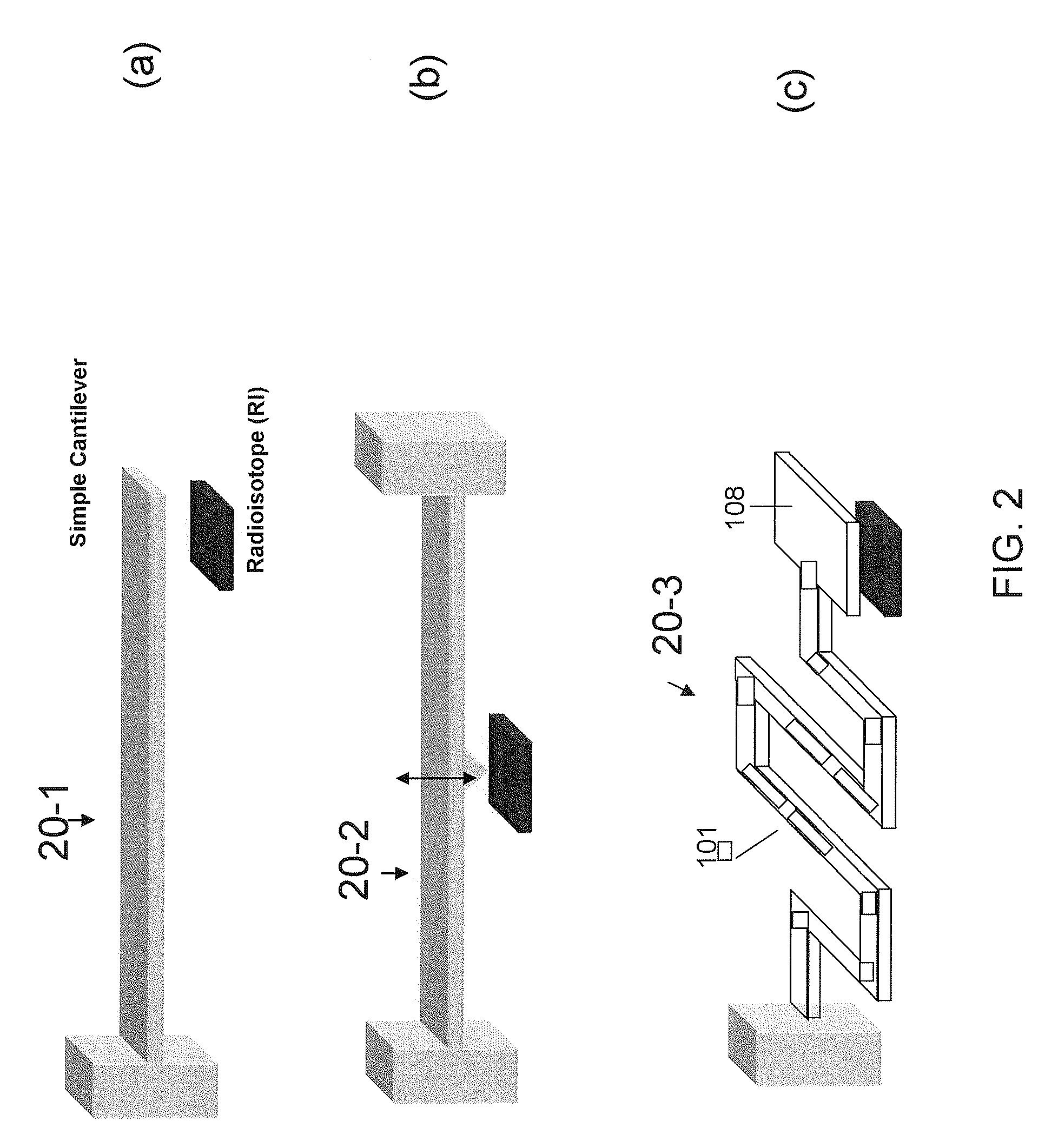
[0038]FIG. 1 schematically shows in cross section a radioisotope-powered, piezoelectric-surface acoustic wave (P-SAW) device 100-1 according to an exemplary embodiment of the invention. The device 100-1 includes a spring assembly 20 comprised of a simple cantilever beam 101 secured at a proximal end 102 thereof to a base 103. A distal end 104 of the beam is free to reciprocate up and down. The apparatus further comprises a radioisotope source 105, a dielectric insulator 106, a bottom electrode 107 and, optionally, a radioactive particle (e.g., electron) collector 108 attached to the distal end of the beam in opposition to the radioactive particle source. Note that the beam itself may have sufficient surface ...


PUM


Abstract

An autonomous, self-powered device includes a radioisotope-powered current impulse generator including a spring assembly comprising a cantilever, and a piezoelectric-surface acoustic wave (P-SAW) structure connected in parallel to the current impulse generator. Positive charges are accumulated on an electrically isolated 63Ni thin film due to the continuous emission of β-particles (electrons), which are collected on the cantilever. The accumulated charge eventually pulls the cantilever into the radioisotope thin-film until electrical discharge occurs. The electrical discharge generates a transient magnetic and electrical field that can excite the RF modes of a cavity in which the electrical discharge occurs. A piezoelectric-SAW resonator is connected to the discharge assembly to control the RF frequency output. A method for generating a tuned RF signal includes inputting an energy pulse to a P-SAW resonator, exciting the resonant frequency thereof, and outputting an RF signal having a frequency tuned to the resonator frequency.

Description

RELATED APPLICATION DATA[0001]The instant application claims priority to U.S. Provisional application Ser. No. 61 / 193,251 filed on Nov. 10, 2008, the subject matter of which is incorporated herein by reference in its entirety.BACKGROUND OF THE INVENTION[0002]1. Field of the Invention[0003]Embodiments of the present invention relate to transponder, telemetry / receiver, and sensor apparatus and associated methods. More particularly, embodiments of the invention are directed to self-powered such apparatus having design-in frequency control and associated methods. Most particularly, embodiments of the invention are directed to a radioisotope-powered, piezoelectric-surface acoustic wave transducer and associated methods.[0004]2. Description of the Related Art[0005]Microelectromechanical systems (MEMS) have become pervasive through various applications in everyday life. The small size of MEMS and their fabrication materials naturally offer the opportunity for the integration of these struc...

Claims


Application Information

Patent Timeline
Patent Type & Authority Applications(United States)
IPC IPC(8): H04Q5/22G21H1/00G06K19/06G01G9/00
CPCG21H1/02H03H9/145H03H9/0542H03B5/326G05D1/028G06K19/0675H02J7/0031H02N2/183
Inventor LAL, AMITTIN, STEVEN
Owner CORNELL UNIVERSITY
Why Eureka
Try Eureka