Liquid ejecting head, liquid ejecting unit, and liquid ejecting apparatus

a liquid ejector and liquid ejector technology, applied in printing, inking apparatus, other printing apparatus, etc., can solve the problems of difficult suppression of sedimentation of liquid components, low bubble discharge efficiency, and inability to uniformly eject ink from all nozzles at the time, and achieve uniform ejecting properties.

Inactive Publication Date: 2011-10-06
SEIKO EPSON CORP
View PDF5 Cites 34 Cited by
  • Summary
  • Abstract
  • Description
  • Claims
  • Application Information

AI Technical Summary

Benefits of technology

[0008]Here, an advantage of some aspects of the invention is to provide a liquid ejecting head including a circulation path which has a more uniform ejection property, a liquid ejecting unit including the corresponding liquid ejecting head, and a liquid ejecting apparatus.

Problems solved by technology

However, in the ink jet recording heads disclosed in JP-A-2009-23289, it is difficult to introduce ink to the downstream side circulation path, so that there are problems in that the bubble discharge efficiency is low and the sedimentation of liquid component is difficult to suppress.
Furthermore, with respect to the ink jet recording head as described above, there is a problem in that ink is not uniformly ejected from all the nozzles at the time of ink ejection.
Meanwhile, such a problem exists in not only a liquid ejecting apparatus using ink jet recording heads but also in a liquid ejecting apparatus using liquid ejecting heads which eject liquids other than ink.

Method used


Image

  • Liquid ejecting head, liquid ejecting unit, and liquid ejecting apparatus
  • Liquid ejecting head, liquid ejecting unit, and liquid ejecting apparatus
  • Liquid ejecting head, liquid ejecting unit, and liquid ejecting apparatus

Examples


Embodiment Construction

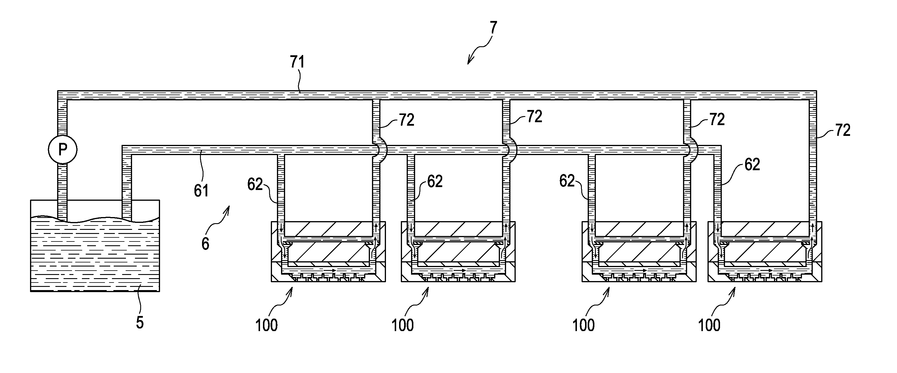
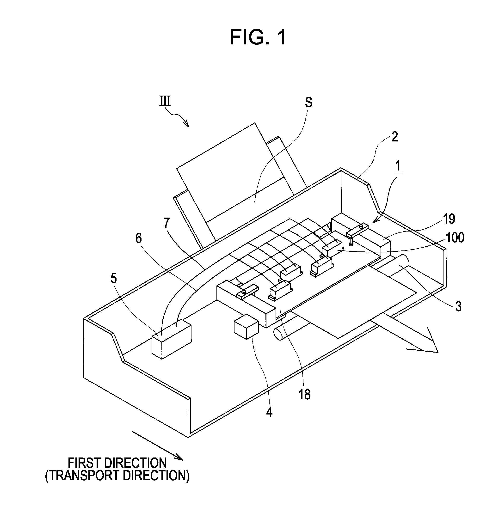
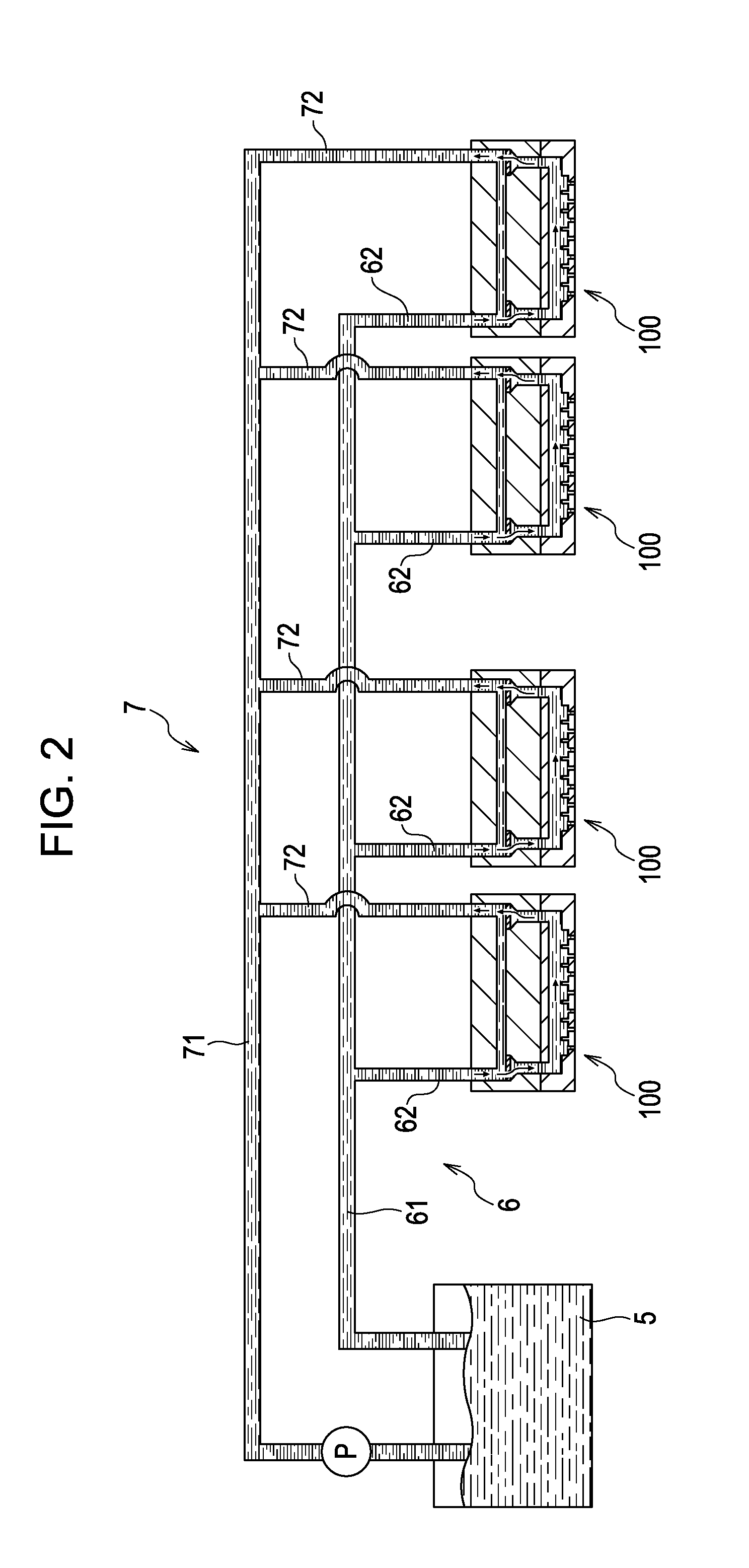
[0021]A liquid ejecting apparatus according to an aspect of the present invention will be described with reference to FIGS. 1 to 6A and 6B. The ink jet recording apparatus according to the embodiment of the invention is a so-called line type ink jet recording apparatus which performs printing on a recorded medium in such a way that liquid ejecting heads are fixed in an ink jet recording apparatus body, and a recording medium, such as a recording paper, is transported in a direction orthogonal to the nozzle column direction. An ink jet recording apparatus III shown in FIG. 1 includes a head unit 1, an apparatus body 2, a feeding roller 3, which is an example of a movement unit, and a control unit 4.

[0022]The head unit 1 includes a frame member 19 attached to a base plate 18 on which a head group (meanwhile, each head group includes four heads 100 in FIG. 1) including a plurality of liquid ejecting heads (hereinafter, refer to heads) 100 is held, and the head unit 1 is fixed to the ap...


PUM


Abstract

A liquid ejecting head includes a plurality of nozzle openings, a first flow path, a supply path, a recovery path, a first filter, a second filter, and a second flow path. The nozzle openings eject a liquid, the first flow path is communicated with the plurality of nozzle openings and the liquid is circulated through the first flow path. The supply path supplies the liquid to the first flow path from the outside, and the recovery path recovers the liquid from the first flow path to the outside. The first filter is provided in the supply path and the second filter is provided in the recovery path. The second flow path connects the supply path provided in the upstream side of the first filter and the recovery path provided in downstream side of the second filter.

Description

[0001]The entire disclosure of Japanese Patent Application No: 2010-084888, filed Apr. 1, 2010 and Japanese Patent Application No: 2010-285975, filed Dec. 22, 2010 are expressly incorporated by reference herein.BACKGROUND[0002]1. Technical Field[0003]The present invention relates to a liquid ejecting head, a liquid ejecting unit, and a liquid ejecting apparatus.[0004]2. Related Art[0005]As an ink jet recording apparatus which is an example of a liquid ejecting apparatus according to the related art, a circulation type ink jet recording apparatus, in which an ink tank separated from ink jet recording heads is provided, and ink is circulated between the ink tank and the ink jet recording heads, has been known (for example, refer to JP-A-2009-23289 (refer to FIG. 3 or the like)).[0006]In the ink jet recording apparatus disclosed in JP-A-2009-23289, a single outward pipe and a single inward pipe are provided in the ink tank, and ink is supplied to each of the recording heads by branchin...

Claims


Application Information

Patent Timeline
Patent Type & Authority Applications(United States)
IPC IPC(8): B41J2/18
CPCB41J2/14233B41J2/1707B41J2202/12B41J2/18B41J29/02B41J2/17563
Inventor UEZAWA, HARUHISA
Owner SEIKO EPSON CORP
Why Eureka
Try Eureka