Passive seismic data acquisition and processing using multi-level sensor arrays

a sensor array and data acquisition technology, applied in the field of passive seismic surveying, can solve problems such as increased signal-to-noise ratio

Inactive Publication Date: 2011-10-06
MICROSEISMIC
View PDF13 Cites 13 Cited by
  • Summary
  • Abstract
  • Description
  • Claims
  • Application Information

AI Technical Summary

Problems solved by technology

In applications for passive seismic emission tomography related to reservoir and/or frac monitoring, typically the dominant sources of noise occur proximate the Earth's surfa

Method used


Image

  • Passive seismic data acquisition and processing using multi-level sensor arrays
  • Passive seismic data acquisition and processing using multi-level sensor arrays
  • Passive seismic data acquisition and processing using multi-level sensor arrays

Examples


Embodiment Construction

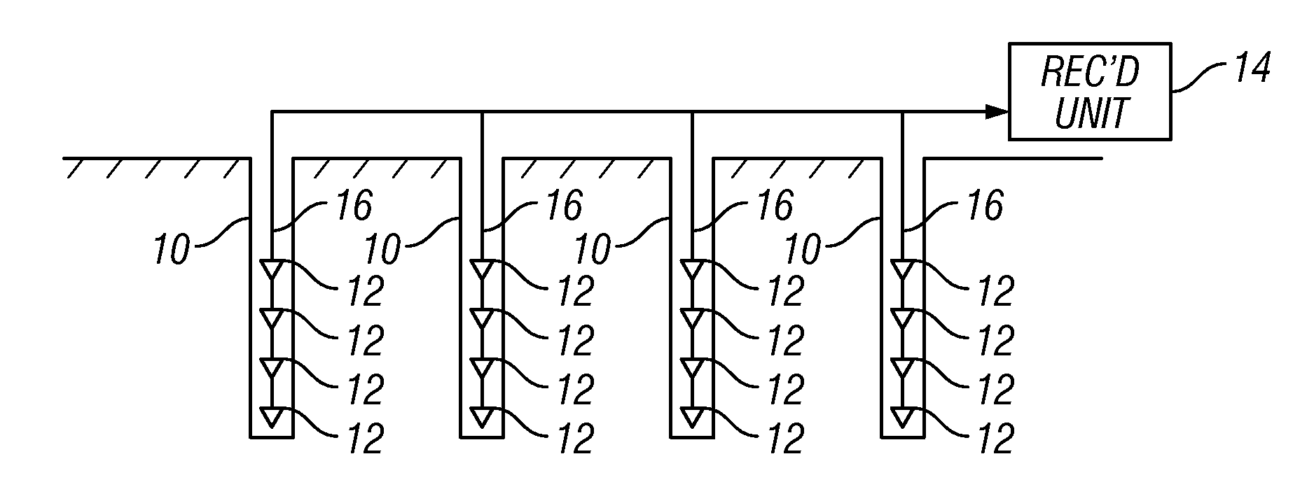
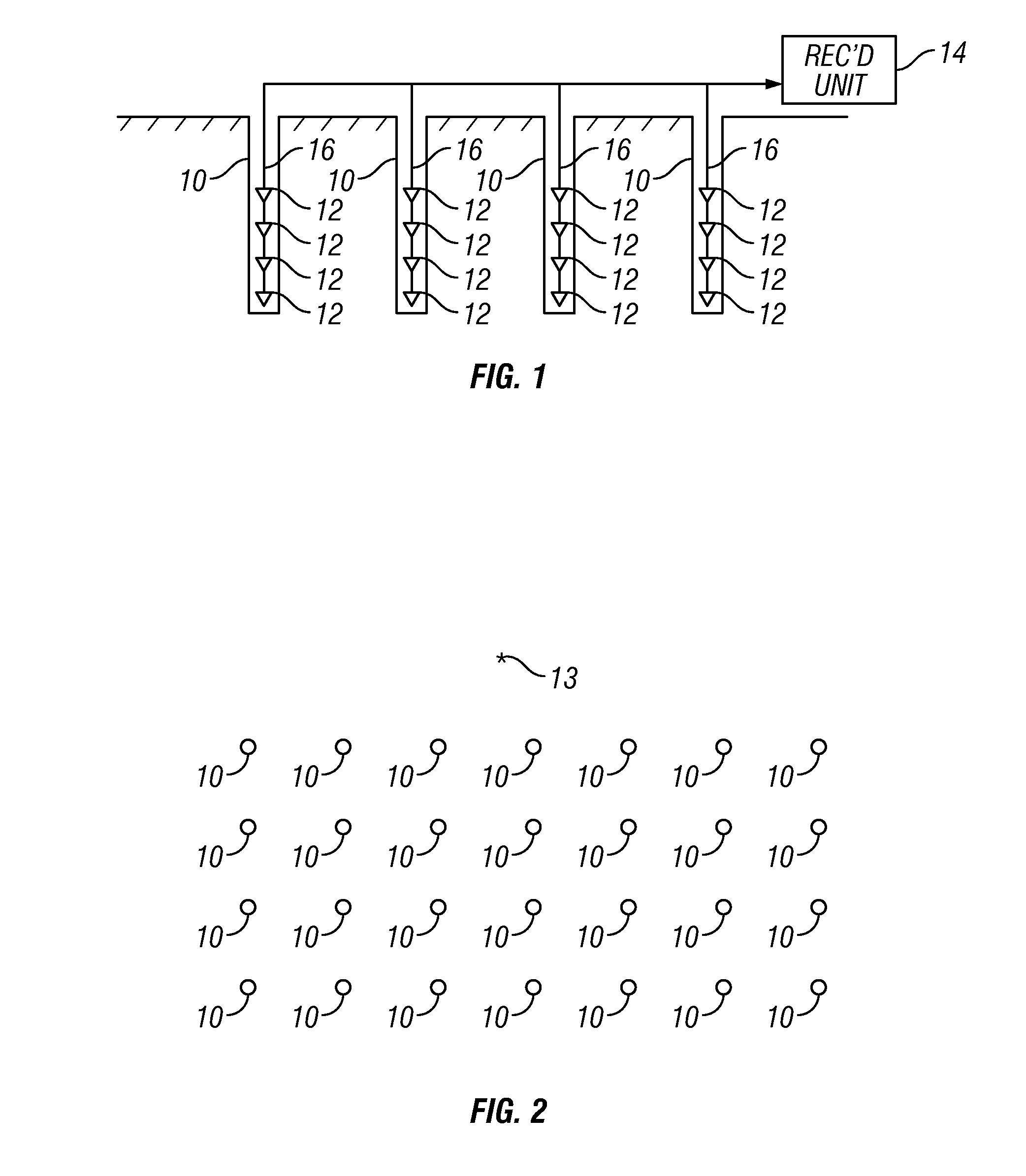
[0016]FIG. 1 shows a cut away view of one line of sensors in a two dimensional array of sensors according to the invention. A plurality of wellbores 10 are drilled to a selected depth below the Earth's surface. In practice, the depth is typically about 100 meters, although different depths may be used. For example, in the presence of very high levels of surface occurring noise, the wellbores may be drilled deeper. In some examples, existing wellbores may be used, for example, wellbores that are no longer used to produce or inject fluid.

[0017]A substantially vertically arranged array of seismic sensors 12 may be placed into each wellbore in the present example. The sensors 12 may be single component or multi-component (three sensitive axis) geophones, for example. The sensors 12 may be inserted by suspending them on a cable 16 and then filling the wellbore 10. In one example, the spacing between adjacent sensors is about 17 meters. The example shown uses four sensors 12 in each verti...


PUM


Abstract

A method for passive seismic surveying includes deploying seismic sensors in a plurality of spatially distributed wellbores disposed above a volume of subsurface formations to be evaluated. The sensors in each wellbore form a line of sensors. Each sensor generate optical or electrical signals in response to seismic amplitude. The seismic signals from each sensor are recorded for a selected period of time. The response of the seismic sensor recordings is beam steered to at least one of a selected point and a selected volume in the subsurface. At least one microseismic event is identified in the beam steered response.

Description

CROSS-REFERENCE TO RELATED APPLICATIONS[0001]Not applicable.STATEMENT REGARDING FEDERALLY SPONSORED RESEARCH OR DEVELOPMENT[0002]Not applicable.BACKGROUND OF THE INVENTION[0003]1. Field of the Invention[0004]The invention relates generally to the field of passive seismic surveying. More specifically, the invention relates to methods for deploying sensors and acquiring passive seismic data to reduce noise and enhance ability to identify microseismic events.[0005]2. Background Art[0006]Passive seismic emission tomography is a process in which an array of seismic sensors is deployed in a selected pattern on the Earth's surface (or on the water bottom in marine surveys) and seismic energy is detected at the sensors that emanates from various seismic events occurring within the Earth's subsurface (“microseismic events”). Processing the signals detected by the sensors is used to determine, among other things, the position in the Earth's subsurface at which the various seismic events took ...

Claims


Application Information

Patent Timeline
IPC IPC(8): G01V1/28
CPCG01V1/008G01V1/006G01V2210/65G01V2210/1234G01V1/288
Inventor THORNTON, MICHAEL P.EISNER, LEODUNCAN, PETER M.
Owner MICROSEISMIC
Why Eureka
Try Eureka