System and Method for Uplink Multi-Antenna Power Control in a Communications System

Active Publication Date: 2011-10-06
FUTUREWEI TECH INC
View PDF8 Cites 102 Cited by
  • Summary
  • Abstract
  • Description
  • Claims
  • Application Information

AI Technical Summary

Benefits of technology

[0010]One advantage disclosed herein is that a number of techniques for multiple uplink transmit antenna power control are presented, allowing power control for channels to be applied on a per-antenna, pe...

Problems solved by technology

Currently used techniques for multiple transmit antenna power control involve the use of extensions of existing sin...

Method used


Image

  • System and Method for Uplink Multi-Antenna Power Control in a Communications System
  • System and Method for Uplink Multi-Antenna Power Control in a Communications System
  • System and Method for Uplink Multi-Antenna Power Control in a Communications System

Examples


Embodiment Construction

[0031]The making and using of the current example embodiments are discussed in detail below. It should be appreciated, however, that the present invention provides many applicable inventive concepts that can be embodied in a wide variety of specific contexts. The specific embodiments discussed are merely illustrative of specific ways to make and use the invention, and do not limit the scope of the invention.

[0032]The present invention will be described with respect to example embodiments in a specific context, namely a 3GPP LTE-Advanced compliant communications system with UEs having multiple transmit antennas. The invention may also be applied, however, to other communications systems that support UEs with multiple transmit antennas, such as WiMAX, and so forth.

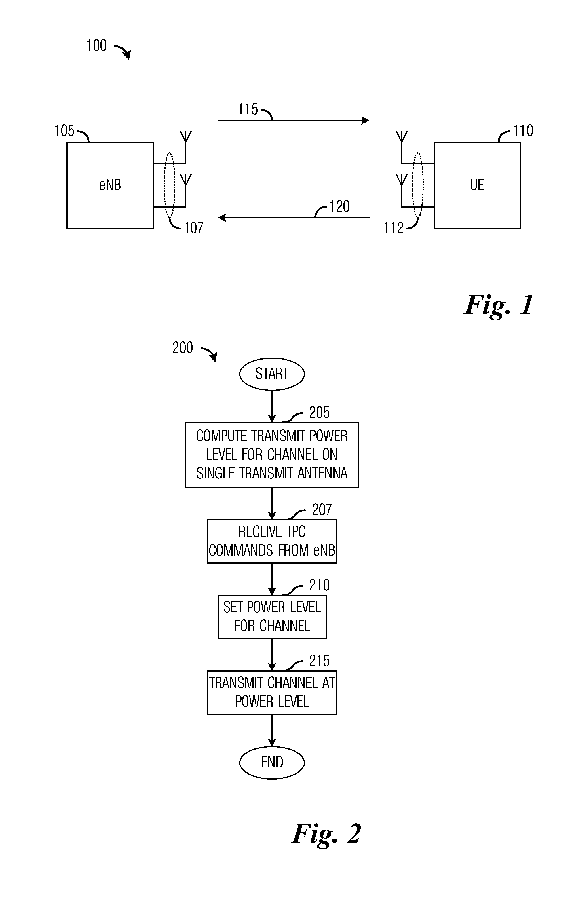
[0033]FIG. 1 illustrates a communications system 100. Communications system 100 includes an eNB 105 and a UE 110 with eNB 105 serving UE 110, i.e., transmissions to and from UE 110 need be allowed by and to go through eNB 10...


PUM


Abstract

A system and method for uplink multi-antenna power control in a communications system are provided. A method for user equipment operations includes determining a transmit power level for transmit antennas of the user equipment having at least two transmit antennas, and setting a power amplifier output level for each of the at least two transmit antennas in accordance with a respective transmit power level.

Description

[0001]This application claims the benefit of U.S. Provisional Application No. 61 / 320,058, filed on Apr. 1, 2010, entitled “Uplink Multi-Antenna Power Control for LTE Advanced,” which application is hereby incorporated herein by reference.TECHNICAL FIELD[0002]The present invention relates generally to digital communications, and more particularly to a system and method for uplink multi-antenna power control in a communications system.BACKGROUND[0003]Generally, a transmit power level of an uplink channel from a User Equipment (UE, also commonly referred to as a Mobile Station, Terminal, User, Subscriber, and so forth) to an enhanced NodeB (eNB, also commonly referred to as a Base Station, NodeB, Controller, and so on) may be set at a determined level to achieve a desired level of uplink performance, help maximize battery life of the UE as well as mitigate interference to other UEs and eNBs, as well as other electronic devices, operating in the general vicinity of the UE. Furthermore, ...

Claims


Application Information

Patent Timeline
IPC IPC(8): H04W52/18H04W24/00
CPCH04B7/0447H04W52/146H04W52/42H04W52/34H01Q1/246H01Q21/28H04W88/02H04W52/20H04W52/52H04B7/0426H04W52/346H04W52/36
Inventor XIAO, WEIMIN
Owner FUTUREWEI TECH INC
Why Eureka
Try Eureka