Dental Implant

a technology for dental implants and implants, applied in dental implants, dental surgery, medical science, etc., can solve the problems of less than 3 permanent nerve damage, and achieve the effect of increasing the quantity and quality of osseous integration

Active Publication Date: 2011-10-06
AIDI BIOMEDICAL LLC
View PDF7 Cites 16 Cited by
  • Summary
  • Abstract
  • Description
  • Claims
  • Application Information

AI Technical Summary

Benefits of technology

[0006]A main object of the present invention is to provide a denta...

Problems solved by technology

However, there are still many problems regarding to safety, patients comfort, prognosis, esthetics and cost which results in only less than 3% of dentists provide this service to ...

Method used


Image

  • Dental Implant
  • Dental Implant
  • Dental Implant

Examples


Embodiment Construction

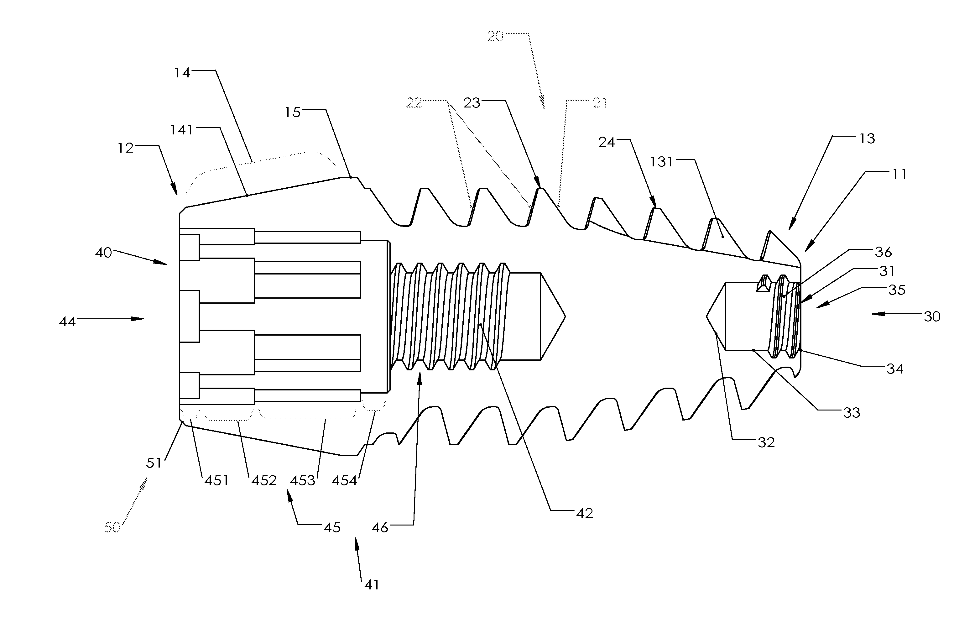
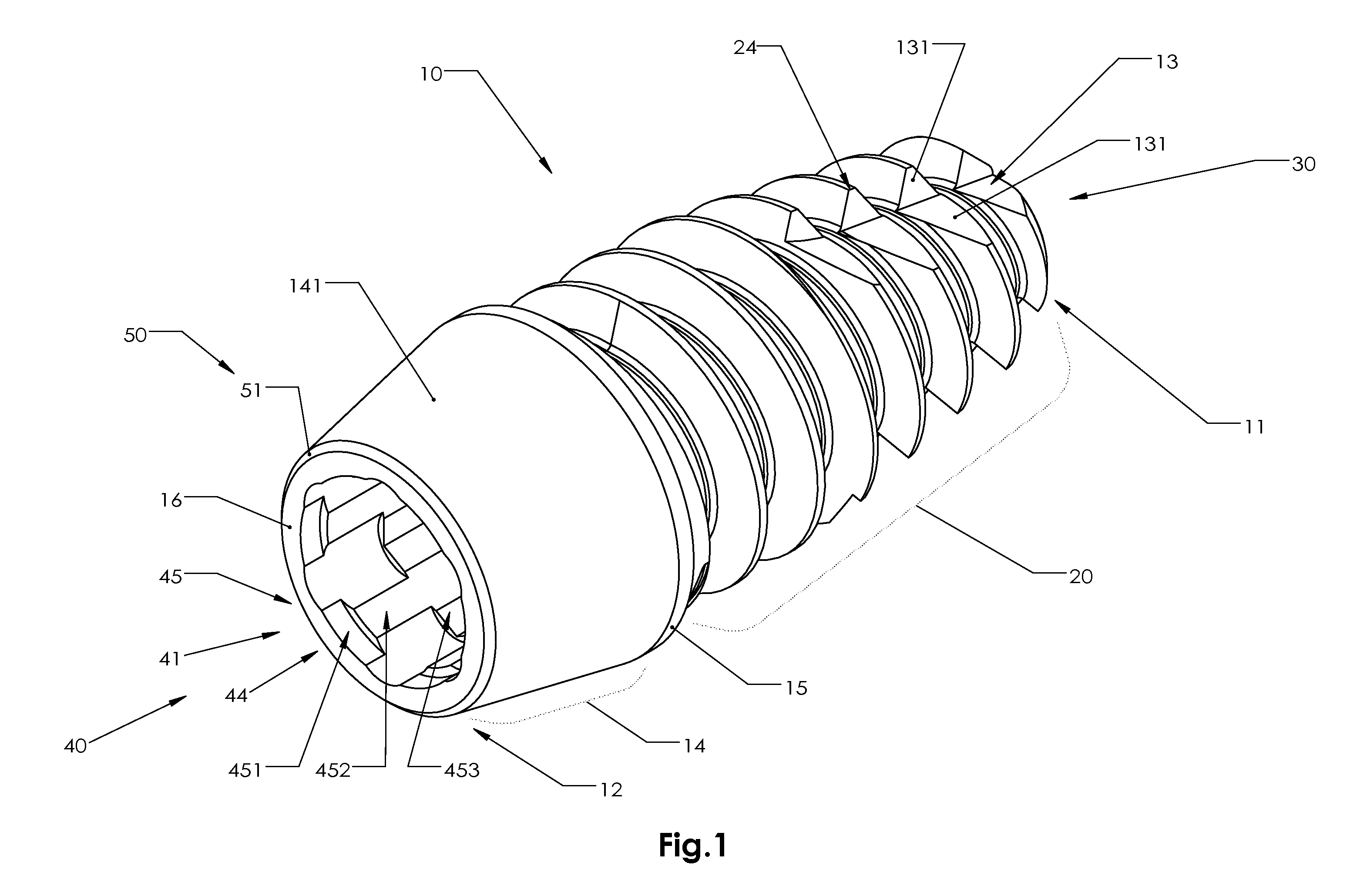
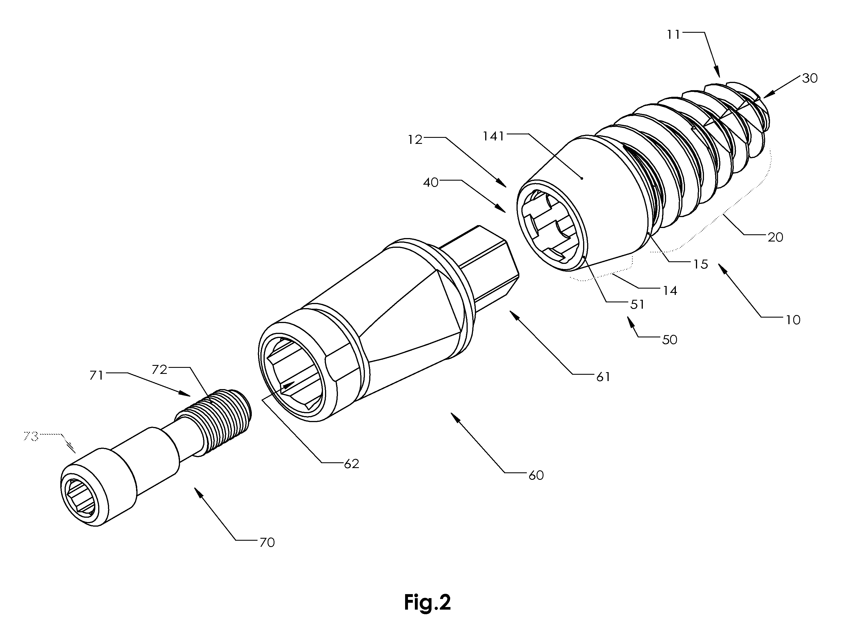
[0036]Referring FIGS. 1 to 3 of the drawings, a dental implant according to a preferred embodiment of the present invention is illustrated, wherein the dental implant comprises a dental implant body 10 which is an irregular cylinder body having a first end 11 for inserting into the bone of the desired position and a second end 12 for integrally connected with an abutment 60 through a bolt 70, wherein an asymmetric thread 20 is provided around the dental implant body 10, an apex lock 30 is formed at the first end, and a hexamaxim lock 40 is provided at the second end.

[0037]The dental implant body 10 has a circular cross section extended between the first end 11 and the second end 12 and a tapered insertion root portion adjacent the first end 11, enabling the dental implant to be more easily inserted into the bone. The second end 12 consists of the ferroembrace 50 and platform 16. The platform 16 is the uppermost portion of the dental implant 10. An abutment will seat on the platform ...


PUM


Abstract

A dental implant includes a dental implant body which is a cylinder body having a first end and a second end, an asymmetric thread being provided around the dental implant body, an apex lock being formed at the first end for inserting into a sinus of a desired position, 3 plurality of apex indentations increasing cutting efficiency, an apexsinoelevation being formed at the lowermost end for elevating a maxillary sinus floor, and a hexamaxim lock being provided at the second end for integrally connected with an abutment through a bolt. The apex lock is a space indented in the first end for enabling new grown bone extending into the apex lock to provide a locking mechanism to ensure integration between the dental implant and the bone. The hexamaxim lock has a lock cavity having a lock opening at the second end for receiving a root of the abutment therein. A ferroembrace is a bevel helps dentist to control esthetics and retention. A cervical slop and cervical steps will help dentist to control the depth of a dental implant to be inserted.

Description

BACKGROUND OF THE PRESENT INVENTION[0001]1. Field of Invention[0002]The present invention relates to dental implants, and particularly to (1) a dental implant having an apex lock for better osseous integration and sinus lift, (2) a hexamaxim lock design, hex-engaging slot, for maximum friction / stability, (3) ferroembrace for additional stability / seating, (4) asymmetrical (sharp) threads providing self drilling effect / reduce resistance of bone—also called Drill Implant, (5) a cervical slop for shifting location of margin design of a restoration, (6) cervical steps for shifting location of margin design of a restoration, (7) 3 plurality of apex indentations for increasing cutting efficiency, (8) apexsinoelevation tip for elevating maxillary sinus floor.[0003]2. Description of Related Arts[0004]A dental implant is an artificial tooth root replacement and is used in prosthetic dentistry to support restorations that resemble a tooth or group of teeth. Multiple millions of implants have b...

Claims


Application Information

Patent Timeline
IPC IPC(8): A61C8/00
CPCA61C8/0039A61C8/006A61C8/0092A61C8/0089A61C8/0022A61C8/0068
Inventor HUNG, WILLIAM Y.S.
Owner AIDI BIOMEDICAL LLC
Why Eureka
Try Eureka