Breast Prosthesis

a prosthesis and breast technology, applied in the field of breast prosthesis, can solve the problems of skin irritation, discomfort of users, and discomfort of wearers, and achieve the effect of avoiding skin irritation and more comfort in wear

Active Publication Date: 2011-10-06
AMOENA MEDIZIN ORTHOPADIE TECHN
View PDF12 Cites 15 Cited by
  • Summary
  • Abstract
  • Description
  • Claims
  • Application Information

AI Technical Summary

Benefits of technology

[0005]It is now the object of the present invention to further develop a breast prosthesis of the initially named type

Problems solved by technology

Problems with respect to comfort in wear can result due to the direct contact on the body surface.
This is perc

Method used


Image

  • Breast Prosthesis
  • Breast Prosthesis
  • Breast Prosthesis

Examples


Embodiment Construction

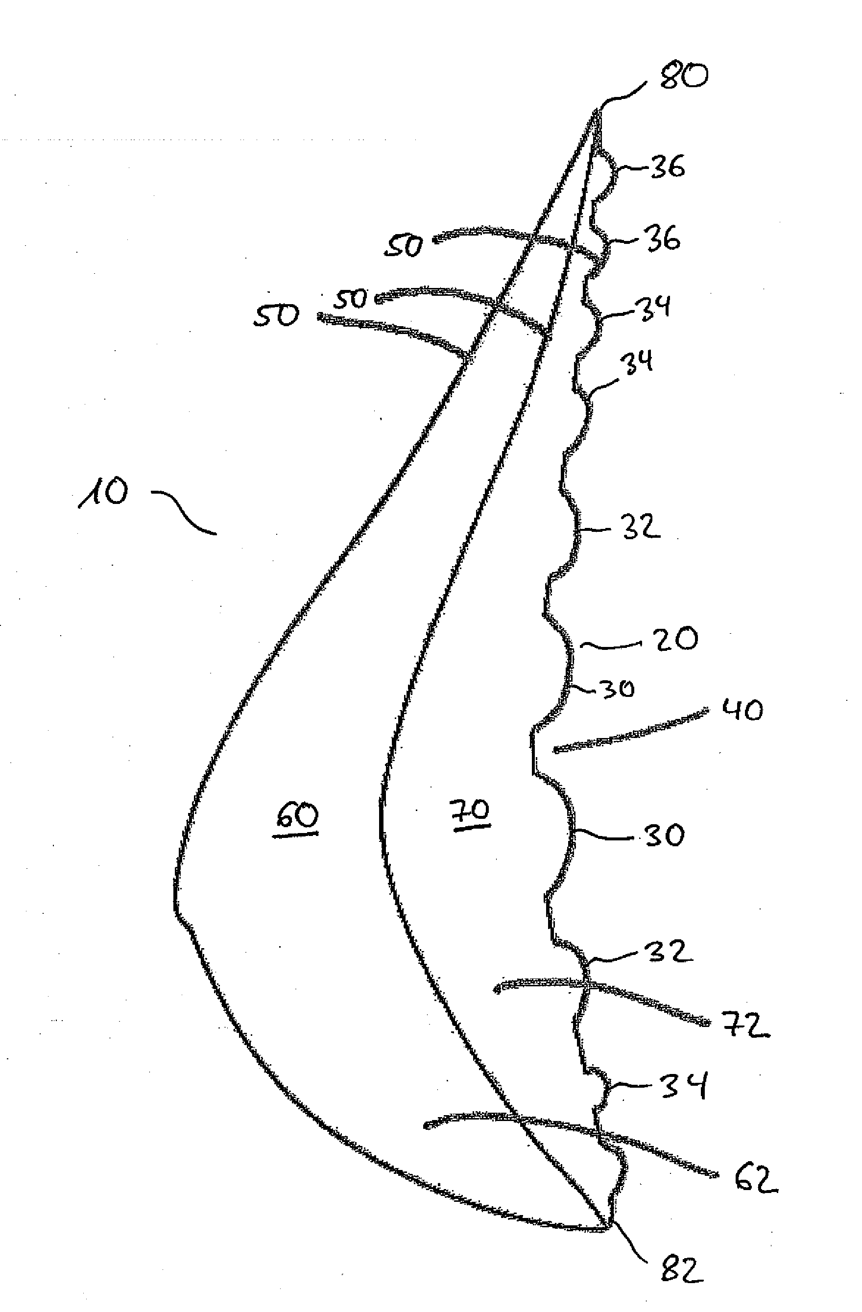
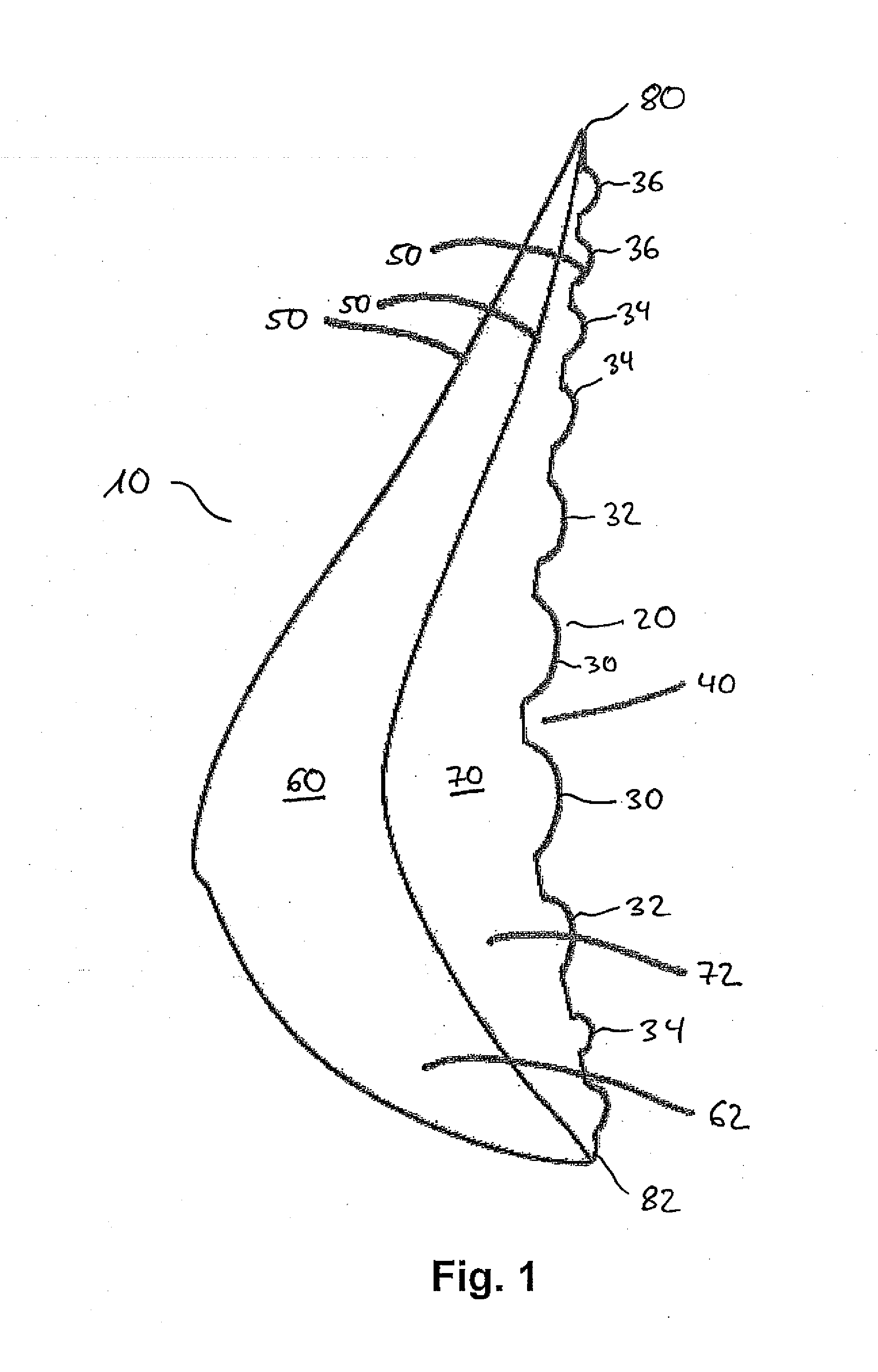
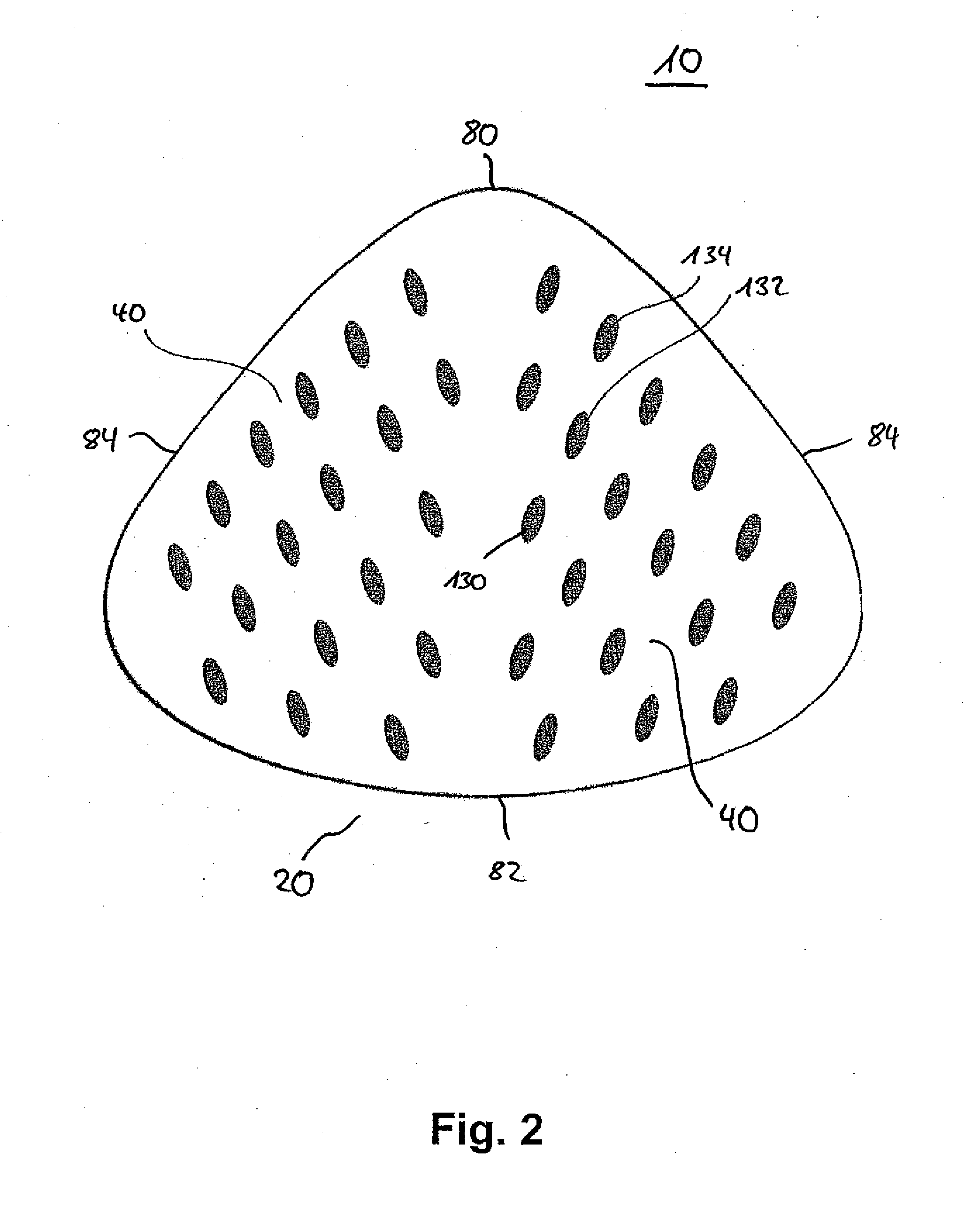
[0032]FIG. 1 shows a sectional representation of the breast prosthesis 10 in a first embodiment in a side view. The breast prosthesis 10 is in this respect based on the shape of a female breast and can be designed as a right breast prosthesis or as a left breast prosthesis. It is equally conceivable that a single embodiment of the breast prosthesis 10 is provided for the right hand side or for the left hand side. The breast prosthesis 10 is in this respect triangular in a frontal view and has convex outer edges or rims 80, 82, 84.

[0033]The breast prosthesis 10 has two chambers 60 and 70, with the first chamber 60 being outwardly disposed or remote from the contact surface 20 and being formed or bounded by two films 50. The films 50 are polyurethane films 50. The chamber 60 is filled with an addition curing two-component silicone rubber compound 62.

[0034]The second chamber 70 is inwardly disposed, i.e. an outer surface 20 of the chamber 70 is a contact surface 20 which is provided fo...


PUM


Abstract

The present invention relates to a breast prosthesis having at least one contact surface which is intended for contact on a body surface, with the contact surface having at least one means by means of which air circulation and/or an exchange of air can be achieved between the contact surface and the body surface.

Description

BACKGROUND OF THE INVENTION[0001]The present invention relates to a breast prosthesis having at least one contact surface which is intended for contact on a body surface.[0002]Breast prostheses for the care of patients after breast surgery, in particular after breast amputations, are already known. Such breast prostheses are usually placed directly onto the body surface and remain there over a fairly long time period in some cases, in particular over the whole day.[0003]Problems with respect to comfort in wear can result due to the direct contact on the body surface. It is in particular possible that perspiration occurs or also overheating of the area of the body surface on which the breast prosthesis lies. This is perceived as unpleasant by the users. Furthermore, irritation of the skin can occur, which is likewise undesirable.[0004]A proposal for the elimination of the aforesaid problems comprises forming the side of the breast prosthesis facing the body as a latent heat store by ...

Claims


Application Information

Patent Timeline
IPC IPC(8): A61F2/12
CPCA61F2/52A61F2002/523A61F2002/5056
Inventor STELTER, NILSREUSCH, MICHAELALEINENBACH, FLORIANSEEHAUS, BRIGITTE
Owner AMOENA MEDIZIN ORTHOPADIE TECHN
Why Eureka
Try Eureka