
Seating structure and methods for the use thereof

a technology of seating structure and seat back, which is applied in the direction of seating, fastening means, stools, etc., can solve the problems of user's tendency to slide forward in the seat, seat and back are not individually adjustable, and are not individually articulated, so as to reduce the amount of hip joint drop during recline, tighten the package space, and reduce the effect of hip drop

Active Publication Date: 2011-10-13
MILLERKNOLL INC
View PDF3 Cites 4 Cited by
  • Summary
  • Abstract
  • Description
  • Claims
  • Application Information

AI Technical Summary

Benefits of technology

[0021]The various aspects and embodiments provide significant advantages over other tilt chairs and seating structures, including chairs and seating structures having backrests, seats and tilt controls. For example, in one preferred embodiment, a rear portion of the seat automatically pivots rearwardly relative to a front portion, with the rear and front portions opening up and forming an angle greater than 180 degrees relative to each other, as the user tilts rearwardly in the chair. In this way, the rear portion provides support for the ischial tuberosities or buttock region of the user and prevents the user from sliding forwardly on the front portion of the seat. By separating the ischial tuberosities or buttock support region from the thigh support region, the entirety of the seat support surface does not have to tipped or pivoted as the user tilts rearwardly. As a result, the hip drop (the amount the hip joint of the user drops during recline) is reduced, thereby providing for tighter package space between the seat surface and tilt control, less energy stored in the tilt (as required to lift the user back up), and lower torques at the given angular travel.
[0022]In addition, the static angle of the back in an upright, neutral position can be easily and quickly adjusted relative to the seat so as to allow the user to customize the fit of the chair for their particular body size and shape. In addition, in one embodiment, the upper portion of the back can be independently pivoted relative to the lower portion of the back, for example when the user arches their back or extends their arms and shoulders rearwardly, while simultaneously supporting the user's back in the arched position. The upper portion will return automatically to a neutral position when the biasing force of the user is relieved.
[0024]In addition, when a leaf spring and adjustable fulcrum are used to apply the return biasing force to the seating structure, the first and second rollers used to support the spring on the base component allow for easy, relatively frictionless movement of the rollers relative to the base component and spring. As such, the position of the fulcrum can be easily adjusted even when the leaf spring is loaded.
[0025]The cam surfaces formed on the spring and the body support structure also provide advantages. In particular, the cam surfaces provide a balanced ride to all types of various users throughout the normal tilting range of the seating structure. In essence, this provides tailored torque outputs as disclosed for example and without limitation in U.S. application Ser. No. 10 / 738,641, filed Dec. 17, 2003 and entitled “Tilt Chair and Methods for the Use Thereof,” the entire disclosure of which is hereby incorporated herein by reference. The cam surfaces eliminate the need for a spring link as disclosed in U.S. application Ser. No. 10 / 738,641, filed Dec. 17, 2003.
[0026]The embodiments of the adjustable seat also provide advantages. For example, the depth of the seat can be adjusted without having to move the entire seat, or in other words, while maintaining a rear portion of the seat in the same position. Such construction avoids the need for additional support members. In addition, the adjustment mechanism can be easily grasped and manipulated by the user to adjust the depth of the seat. Moreover the curved front portion of the seat provides transitional support for the user's legs when sitting down or standing up from the chair. At the same time, the curved portion is relatively flexible, thereby avoiding pressure points along the thighs of the user.

Problems solved by technology

Typically, however, the seat and back are not individually adjustable, and are not individually articulated during tilting.
As such, when a user tilts rearwardly in the chair, the user may tend to slide forward in the seat, even when tilting rearwardly.
At the same time, any adjustment of the depth of the seat, measured from the front leading edge to the rear thereof, typically is provided by moving the entirety of the rigid, unitary seat in a fore-aft direction, which can lead to an unsightly gap forming at the rear of the seat and can also form a pinch point at that location.
In typical tilt chairs, a static angular position of the chair back relative to the seat is typically fixed when the chair is in an unloaded upright position, which may not be particularly well suited for a wide range of users.
As such, the chair back does not allow the user a full range of motion, precluding for example the ability of the user to stretch or arch their back in a concave contour.
The mechanisms used to adjust the load on the spring(s), or the load capability of the spring(s), typically are complicated, and / or require multiple, excessive rotations of a knob or other grippable member to obtain the desired setting.
Moreover, the chairs lack any indicia for the user to determine the setting of the return force of the spring before the user sits or applies a load to the backrest.
Moreover, such tilt chairs often do not provide a balanced ride throughout the range of tilting motion of the chair.
Specifically, the restoring force or torque of the chair, and in particular the spring, does not match the force or torque applied by the user throughout the tilting range.
Moreover, such balance typically cannot be achieved for a variety of users having different weights and body sizes.

Method used


Image

  • Seating structure and methods for the use thereof
  • Seating structure and methods for the use thereof
  • Seating structure and methods for the use thereof

Examples


Embodiment Construction

General:

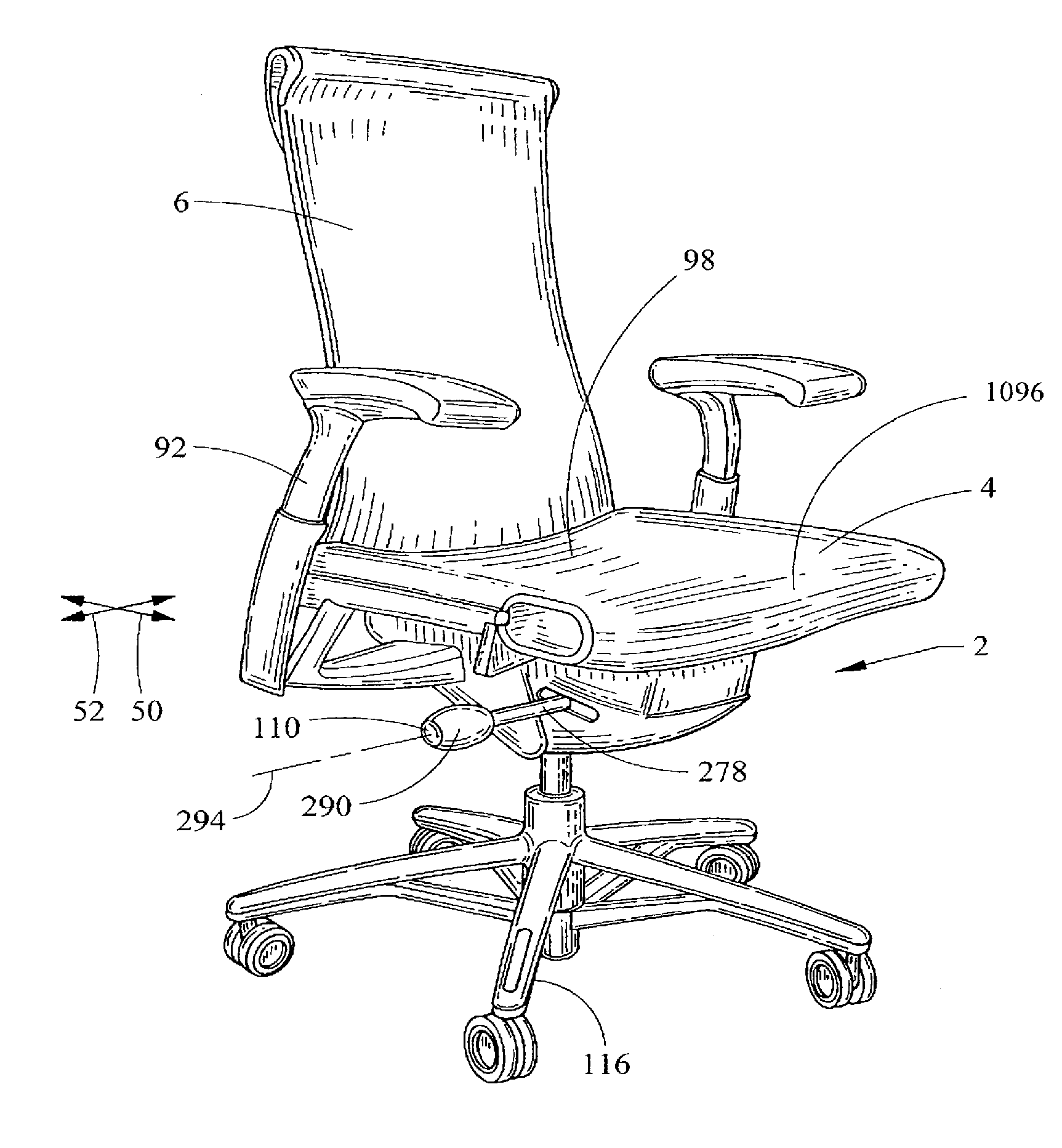
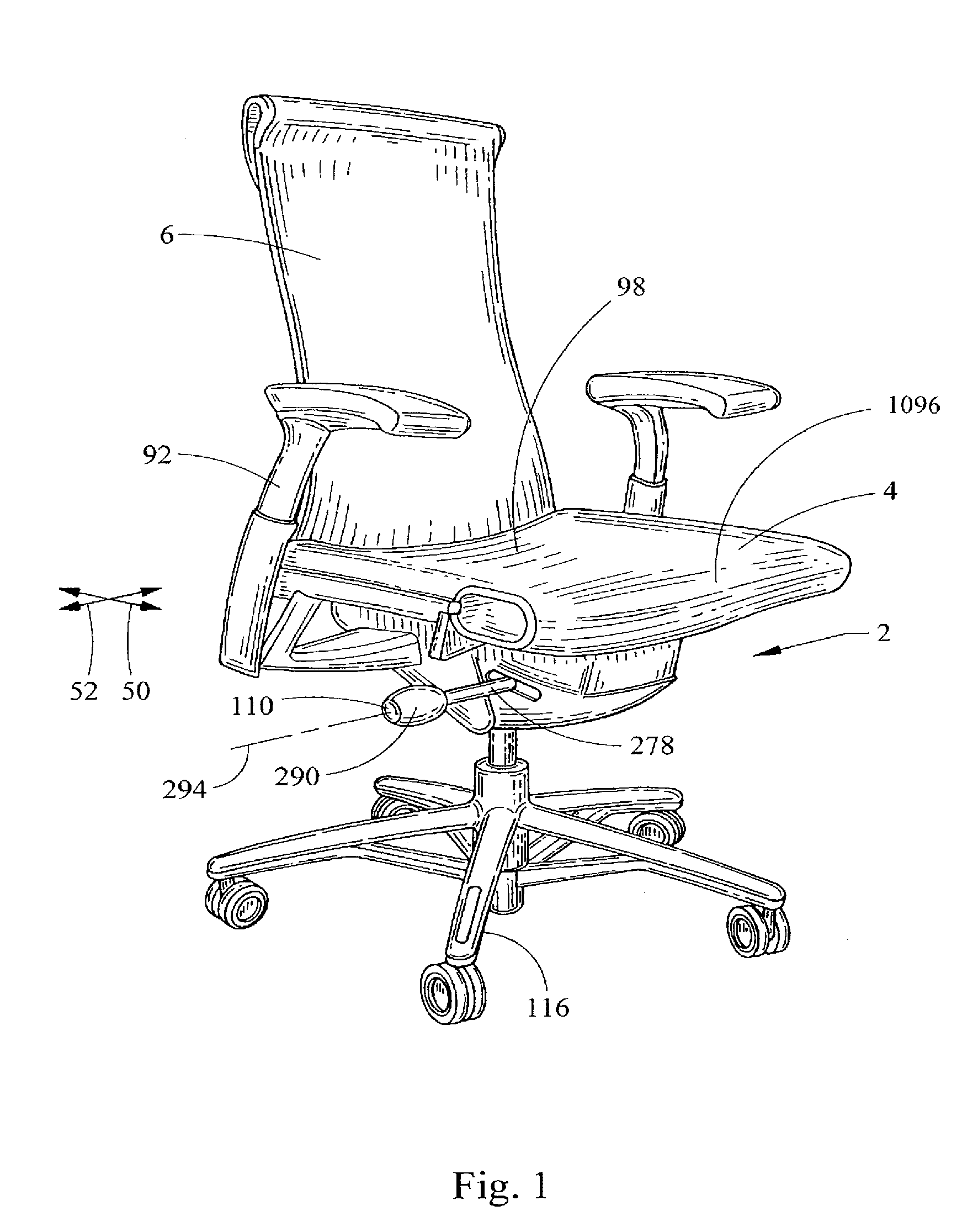
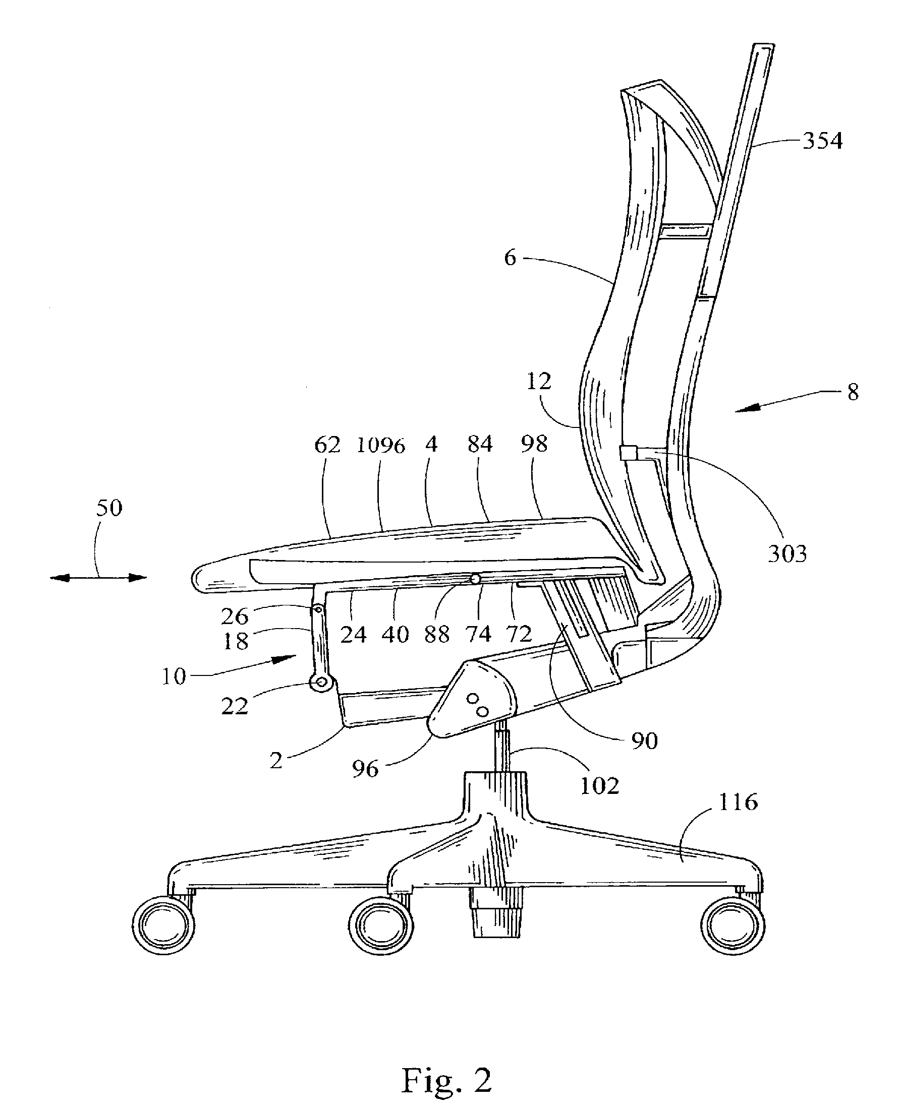
[0135]The terms “longitudinal” and “lateral” as used herein are intended to indicate the directions 50, 52 of the chair from front to back and from side to side, respectively. Similarly, the terms “front”, “side”, “back”, “forwardly”, “rearwardly”, “upwardly” and “downwardly” as used herein are intended to indicate the various directions and portions of the chair as normally understood when viewed from the perspective of a user sitting in the chair. It should be understood that the terms “mounted,”“connected”, “coupled,”“supported by,” and variations thereof, refer to two or more members or components that are joined, engaged or abutted, whether directly or indirectly, for example, by way of another component or member, and further that the two or more members, or intervening member(s) can be joined by being integrally formed, or by way of various fastening devices, including for example and without limitation, mechanical fasteners, adhesives, welding, press fit, bent-over t...


PUM

PropertyMeasurementUnit
angleaaaaaaaaaa
angleaaaaaaaaaa
angleaaaaaaaaaa

Abstract

A seat with an adjustable seat depth is also provided, along with various methods for operating the different aspects and embodiments of the seating structure. In one embodiment, a seating structure includes a support structure and a carriage moveably supported by the support structure. The carriage is moveable relative to the support structure in opposite first and second longitudinal directions. A flexible body support member has a first portion coupled to the support structure, a second portion coupled to the carriage, and a third curved portion positioned between the first and second portions. The third portion is moveable toward and away from the support structure as the carriage is moved relative to the support structure in the first and second directions respectively.

Description

[0001]This application is a continuation of U.S. application Ser. No. 12 / 012,002, filed Jan. 28, 2008, which claims the benefit of U.S. Provisional Application No. 60 / 898,421, filed Jan. 29, 2007, the entire disclosures of which are hereby incorporated herein by reference.FIELD OF THE INVENTION[0002]The present invention relates generally to seating structures, and in particular, to a chair having unique kinematics, a body supporting seat and back, and an adjustable seat depth, and methods for using and / or adjusting the chair, including without limitation one or more of the seat and backrest.BACKGROUND[0003]Chairs of the type typically used in offices and the like are usually configured to allow tilting of the seat and backrest as a unit, or to permit tilting of the backrest relative to the seat. Typically, however, the seat and back are not individually adjustable, and are not individually articulated during tilting. Such chairs therefore sometimes cannot be easily adjusted or cust...

Claims


Application Information

Patent Timeline
Patent Type & Authority Applications(United States)
IPC IPC(8): A47C7/14A47C3/00
CPCA47C1/023A47C1/03255A47C1/03266A47C1/03277A47C7/024A47C7/027Y10T29/49954A47C7/38A47C7/40A47C7/405A47C3/00Y10T403/7039A47C7/14A47C7/144F16B2200/10A47C7/462
Inventor ALDRICH, JOHN F.BRILL, RYAN S.SLAGH, JAMES D.WEBER, JEFFREY A.
Owner MILLERKNOLL INC
Learn More