RF feed network for modular active aperture electronically steered arrays

a technology of electronic steered arrays and feed networks, applied in direction finders using radio waves, instruments, reradiation, etc., can solve the problems of relative preventing the use of phased arrays in all but the most specialized applications, and major cost drivers for assembly and components, especially for active transmit/receive channels, to achieve the effect of high cost of phased arrays

Active Publication Date: 2011-10-13
RAYTHEON CO
View PDF4 Cites 88 Cited by
  • Summary
  • Abstract
  • Description
  • Claims
  • Application Information

AI Technical Summary

Benefits of technology

[0013]As mentioned above, the relatively high cost of phased arrays has precluded the use of phased arrays in all but the most specialized applications. Assembly and component costs, particularly for active transmit / receive channels, are major cost drivers. It would be advantageous to provide a sub-array for an Active Electronically Scanned Array (AESA) that is compact, which can be manufactured in a cost-effective manner and that can be used interchangeably to assemble an AESA.

Problems solved by technology

As mentioned above, the relatively high cost of phased arrays has precluded the use of phased arrays in all but the most specialized applications.
Assembly and component costs, particularly for active transmit / receive channels, are major cost drivers.

Method used


Image

  • RF feed network for modular active aperture electronically steered arrays
  • RF feed network for modular active aperture electronically steered arrays
  • RF feed network for modular active aperture electronically steered arrays

Examples


Embodiment Construction

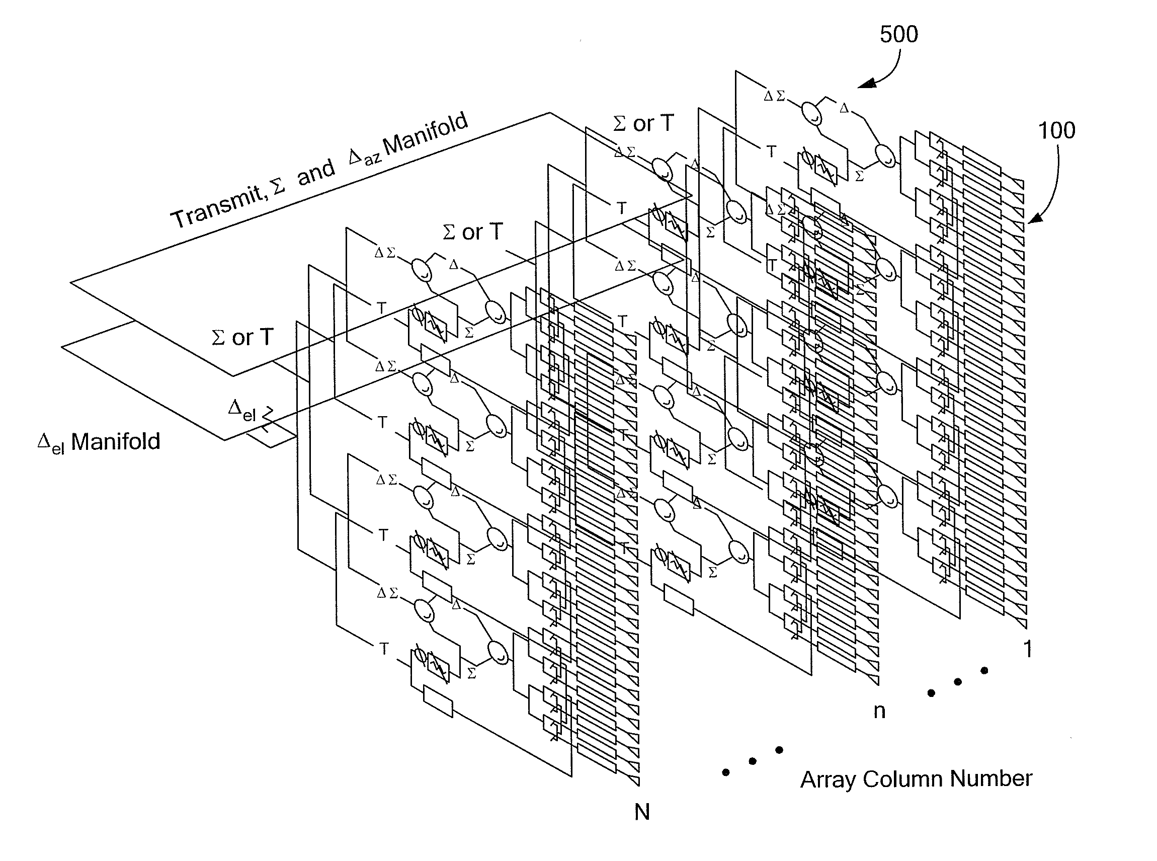
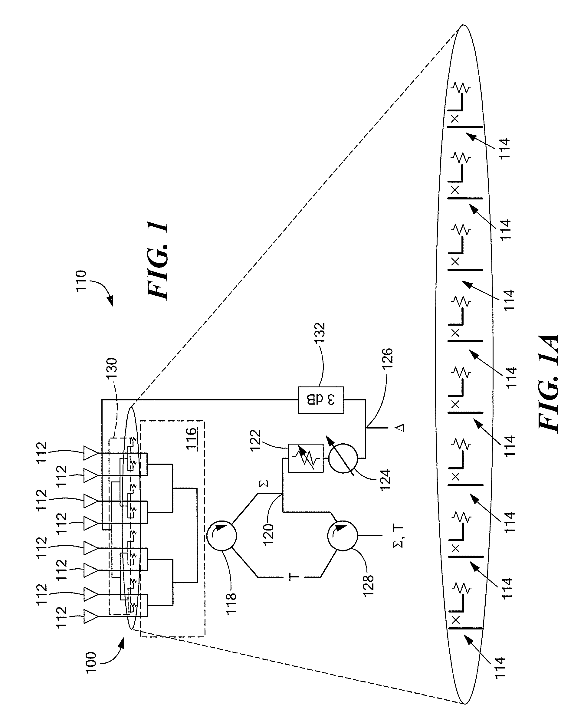
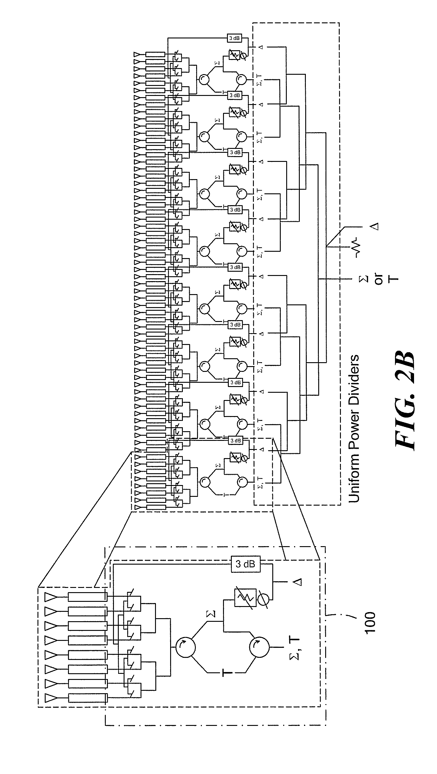
[0032]Before describing the various embodiments of the invention, some introductory concepts and terminology are explained. A “brick” type architecture refers to radio frequency (RF) signals and power signals fed to active components in the phased array that are generally distributed in a plane that is perpendicular to a plane coincident with (or defined by) the antenna aperture. A “panel array” (or more simply “panel”) refers to a multilayer printed wiring board (PWB) which includes an array of antenna elements (or more simply “radiating elements” or “radiators”), as well as RF, logic and DC distribution circuits in one highly integrated PWB. A panel is also sometimes referred to herein as a tile array (or more simply, a “tile”).

[0033]An array antenna may be provided from a single panel (tile or brick array) or from a plurality of panels of tile or brick arrays. In the case where an array antenna is provided from a plurality of panels, a single one of the plurality of panels is som...


PUM


Abstract

A feed network for an antenna subarray includes a first feed arrangement having an sum output, a second feed arrangement having an delta output, a fixed attenuator having a first port and a second port, the first port connected to the delta output of the second feed arrangement, a first power divider/combiner having a first and second port and a third port; the first port connected to the second port of the fixed attenuator, a variable phase shifter having a first port and a second port, the first port connected to the second port of the power divider/combiner, a variable attenuator having a first port and a second port, the first port connected to the second port of the variable phase shifter, a second power divider/combiner having a first and second port and a third port; the first port connected to the second port of the fixed attenuator, a first circulator having a first port, a second port and a third port, the first port connected to the sum output of the first feed arrangement, and a third power divider/combiner having a first and second port and a third port; the third port connected to the second port of the circulator and the second port connected to the second port of the variable attenuator.

Description

FIELD OF THE INVENTION[0001]This invention relates generally to phased array antennas adapted for volume production at a relatively low cost and more particularly Active Electronically Steered Arrays (AESAs) including a plurality of subarray panels where each one of the subarray panels are interchangeable.BACKGROUND OF THE INVENTION[0002]Phased array antennas include a plurality of antenna elements spaced apart from each other by known distances coupled through a plurality of phase shifter circuits to either or both of a transmitter or receiver. There is a desire to lower acquisition and life cycle costs of radio frequency (RE) systems which utilize phased array antennas (or more simply “phased arrays”). One way to reduce costs when fabricating RF systems is to utilize printed wiring boards (PWBs) (also sometimes referred to as printed circuit boards or PCBs) which allow use of more effective manufacturing techniques.[0003]As is known, phased array antenna systems are adapted to pro...

Claims


Application Information

Patent Timeline
Patent Type & Authority Applications(United States)
IPC IPC(8): H01P5/12
CPCG01S13/4463H01Q25/02H01Q21/0025
Inventor POZGAY, JEROME H.
Owner RAYTHEON CO
Why Eureka
Try Eureka