Audio signal processing apparatus, audio signal processing method, and program

a technology of audio signal and processing method, applied in the field of audio signal processing apparatus, audio signal processing method, program, can solve the problem of large processing burden, achieve the effect of simple and easy detection of taps, increasing the energy level of low-frequency components of microphone input signals, and simplifying the process

Inactive Publication Date: 2011-10-13
SONY CORP
View PDF3 Cites 24 Cited by
  • Summary
  • Abstract
  • Description
  • Claims
  • Application Information

AI Technical Summary

Benefits of technology

[0007]As in Japanese Unexamined Patent Application Publication No. 2008-166897, since a microphone can also be used as an input device, this use contributes to a reduction in the number of operation keys of the apparatus housing and to improved ease of use.
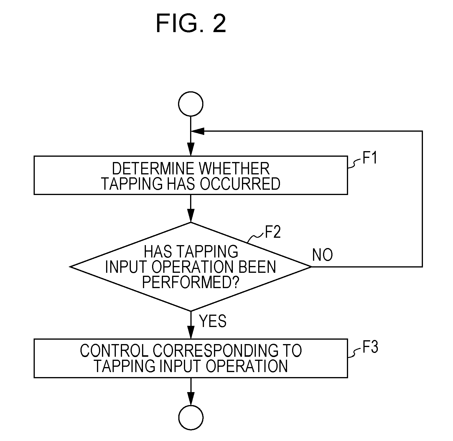
[0013]Accordingly, it is desirable to perform all processes and determinations by time axis signal processing, decrease the number of calculations, and shorten the time until detection at the same time in a case where an operation input is to be detected from an audio signal of a microphone input caused by tapping performed by a user.
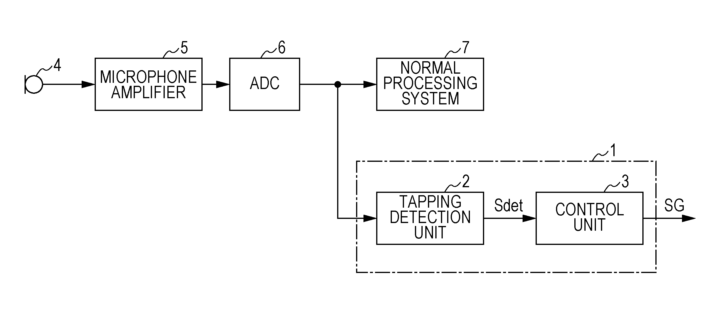
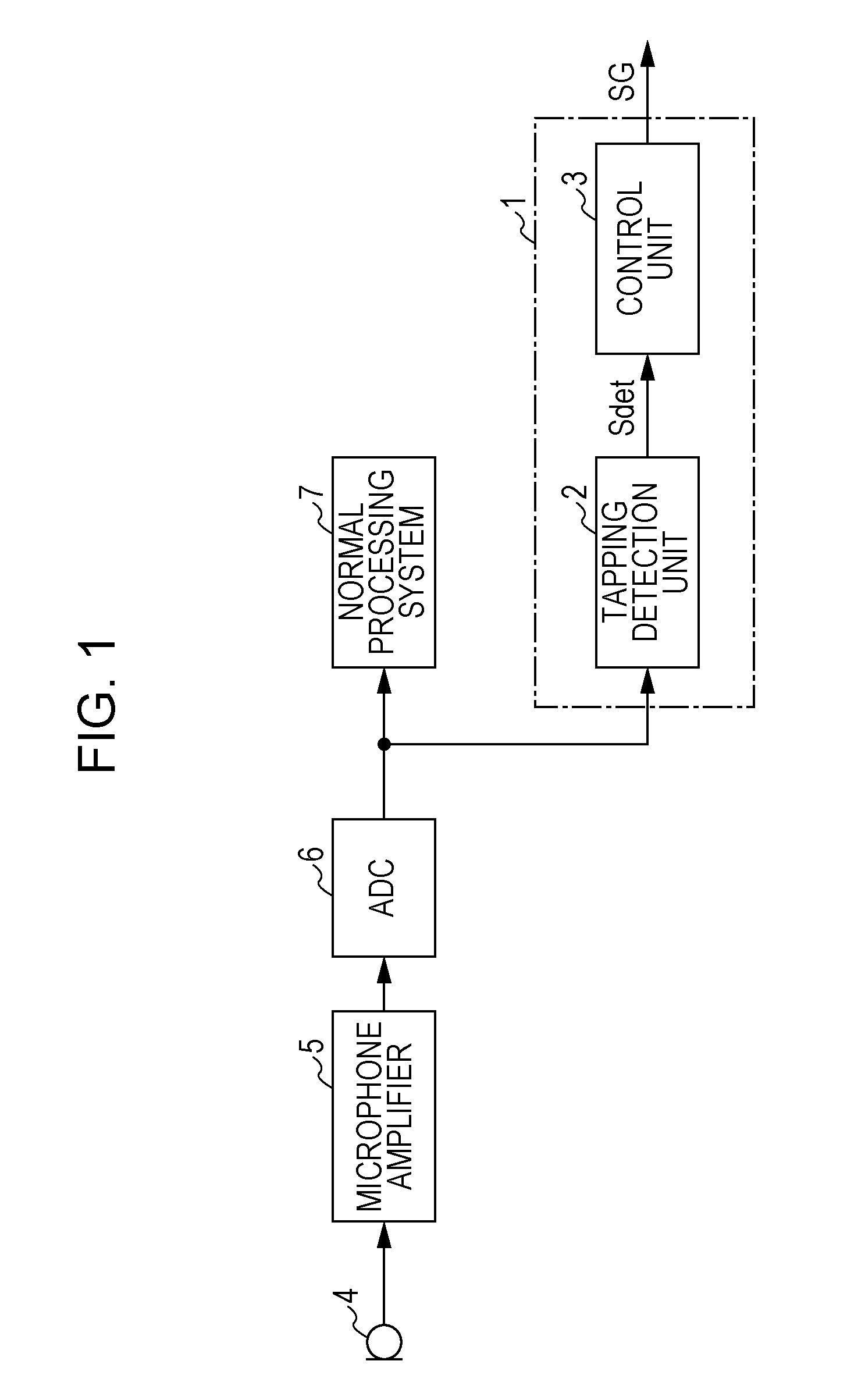
[0023]In the case where a tap has occurred, the energy level (amplitude) of low-frequency components of a microphone input signal increases. Therefore, it becomes possible to detect a tap simply and easily without performing waveform analysis by monitoring the energy of low-frequency components of an audio signal.
[0024]According to an embodiment of the present invention, it is possible to detect a user operation performed by tapping on the basis of a microphone input audio signal by a simplified process. Consequently, it is possible to reduce a processing burden for detecting operation and reduce cost as a result of the reduction.
[0025]Furthermore, the simplified process allows the operation detection time period to be shortened, and a device operation with a satisfactory response becomes possible.

Problems solved by technology

This takes a lot of resources (number of calculations) of a central processing unit (CPU) or a digital signal processor (DSP) as a computation processing device, and the processing burden is large.

Method used


Image

  • Audio signal processing apparatus, audio signal processing method, and program
  • Audio signal processing apparatus, audio signal processing method, and program
  • Audio signal processing apparatus, audio signal processing method, and program

Examples


configuration example i

[0129]Hereinafter, the configuration and operation of the tapping detection unit 37 will be described. Here, first, a configuration example I shown in FIG. 5 will be described.

[0130]Configuration example I is a configuration example in which a tapping is detected in common with regard to the audio signals SmL and SmR from the mics 12L and 12R.

[0131]The tapping detection unit 37 includes an adder 51, a low-pass filter 52, a conversion-to-absolute-value circuit 53, a low-pass filter 54, and a determination processing unit 55.

[0132]The audio signals SmL and SmR from the mics 12L and 12R are added by the adder 51 and are input to the low-pass filter 52. The cut-off frequency of the low-pass filter 52 is set at fc1. For example, it is set that fc1=100 Hz.

[0133]The low-frequency components with regard to the added signal of the audio signals SmL and SmR output from the low-pass filter 52 are converted into an absolute value by the conversion-to-absolute-value circuit 53.

[0134]The signal t...

configuration example ii

[0217]A tapping detection unit 37 as a configuration example II will be described with reference to FIG. 10.

[0218]The configuration example II is an example in which the L channel and the R channel, that is, the mics 12L and 12R, can be assigned to separate operations, respectively.

[0219]For example, the configuration example II is a configuration example in which the tapping of the mic 12L can be set as a volume up and the tapping of the mic 12R as a volume down.

[0220]As shown in FIG. 10, the tapping detection unit 37 adopts a tapping detection configuration of two independent systems using an L channel and an R channel.

[0221]That is, a low-pass filter 52L, a conversion-to-absolute-value circuit 53L, a low-pass filter 54L, and a determination processing unit 55L are provided for the audio signal SmL from the mic 12L. Furthermore, a low-pass filter 52R, a conversion-to-absolute-value circuit 53R, a low-pass filter 54R, and a determination processing unit 55R are provided for the aud...

configuration example iii

CONFIGURATION EXAMPLE III

[0228]Next, a configuration example III is shown in FIG. 11. Similarly to the configuration example II, the configuration example III is an example in which the L channel and the R channel, that is, the mics 12L and 12R, can be assigned to separate operations, respectively. In the case of the configuration example II, since the tapping detection unit 37 is simply installed with two tapping detection processing systems, the burden caused by the configuration is increased. The configuration example III is an example in which the burden caused by the configuration can be reduced.

[0229]In the configuration example III, the tapping detection unit 37 performs a channel determination process for making a determination as to whether the channel contains tapping sound between the audio signals SmL and SmR of a plurality of channels, and performs an energy increase / decrease determination process for an audio signal in which audio signals of a plurality of channels ar...


PUM


Abstract

An audio signal processing apparatus includes a tapping detection unit to which an audio signal picked up by a microphone is input and that detects a tapping input operation on the basis of an energy increase / decrease determination process for making a determination as to whether an increase and a decrease of an energy level of low-frequency components of the audio signal occur within a first time period; and a control unit that performs a certain control process that is set for a tapping input operation in response to a tapping input operation being detected by the tapping detection unit.

Description

BACKGROUND OF THE INVENTION[0001]1. Field of the Invention[0002]The present invention relates to an audio signal processing apparatus that detects an operation input of a user by using an audio signal picked up by a microphone, and to an audio signal processing method for use therewith. Furthermore, the present invention relates to a program for implementing such an audio signal processing apparatus and audio signal processing method.[0003]2. Description of the Related Art[0004]In various electronic apparatuses, as devices for inputting operations of a user, operation keys, a keyboard, a mouse, operation dials, a touch panel, and the like are used.[0005]Usually, these operation devices are installed in correspondence with the functions of the electronic apparatuses. On the other hand, depending on the functions and usage of the electronic apparatuses, there has been a demand for making the number of operation keys as small as possible and making operations easier to perform and effi...

Claims


Application Information

Patent Timeline
Patent Type & Authority Applications(United States)
IPC IPC(8): H04R29/00
CPCG06F2200/1636G06F1/1626H04R1/1041H04R29/00H04R2225/61H04R3/04
Inventor ASADA, KOHEIKITAZAWA, YUJI
Owner SONY CORP
Why Eureka
Try Eureka