Ct spectral calibration

a spectral calibration and imaging system technology, applied in the field of noninvasive imaging, can solve the problems of increasing difficulty in performing spectral calibrations by attaching the phantom at the edge of the patient table, and the system may be subject to various artifacts

Active Publication Date: 2011-10-13
GENERAL ELECTRIC CO
View PDF3 Cites 23 Cited by
  • Summary
  • Abstract
  • Description
  • Claims
  • Application Information

AI Technical Summary

Problems solved by technology

Such a CT system may be subject to various artifacts, such as beam hardening artifacts, ring/band artifacts, and/or scatter-induced artifacts.
The increased

Method used


Image

  • Ct spectral calibration
  • Ct spectral calibration
  • Ct spectral calibration

Examples


Embodiment Construction

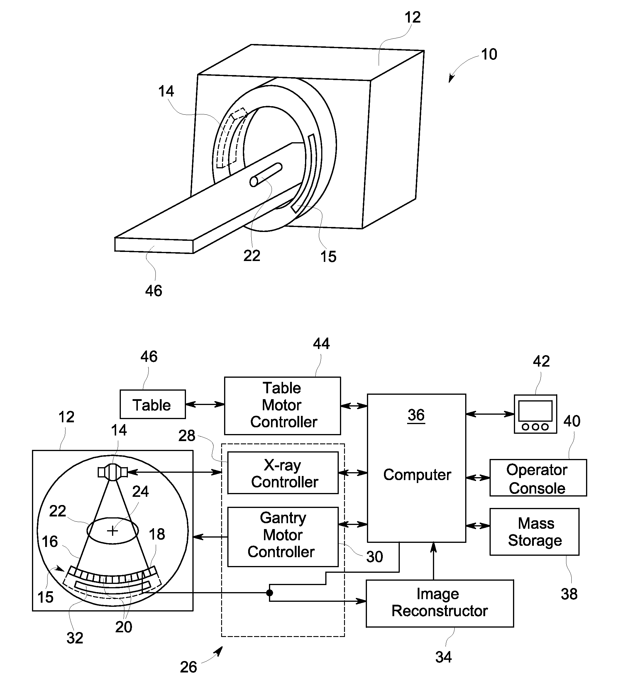
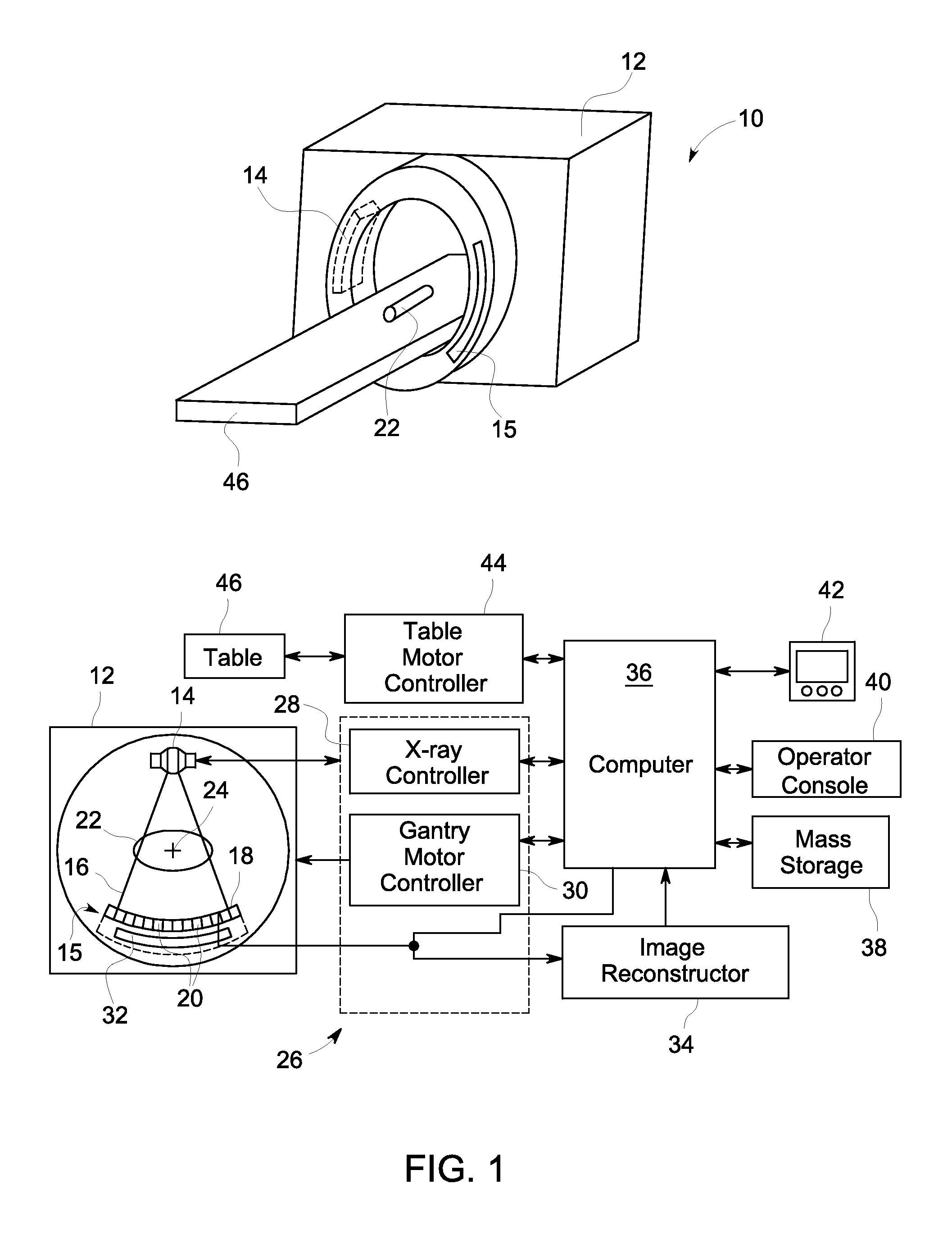
[0013]The present disclosure provides for using large scan phantoms for performing spectral calibration of a CT imaging system. In accordance with the present approach, a phantom may be positioned on the support table during the calibration process. Contributions from the table to the acquired calibration data are removed from the calibration measurements as part of calibration process. In this manner, the CT system may undergo spectral calibration even though the calibration scan data initially includes data corresponding to other structures in addition to the calibration phantom.

[0014]With the foregoing in mind and in accordance with one embodiment, a CT imaging system is provided. The present discussion is generally provided in the context of a 3rd generation CT system, however, the present disclosure is equally applicable to other systems. For simplicity, the present discussion generally describes the use of detectors and X-ray imaging systems in a medical imaging context. Howev...


PUM


Abstract

The present disclosure relates to the performing spectral calibration of a CT imaging system. In accordance with certain embodiments, spectral calibration phantoms are scanned while positioned on a table in the imaging volume of the CT imaging system. The scans of the calibration phantoms, in conjunction with air sans performed on the CT imaging system, are used to derive information about the deviation of the measured phantom scans from an ideal. The deviation information is in turn used to derive spectral calibration vectors that may be used with the CT imaging system.

Description

CROSS-REFERENCE TO RELATED APPLICATIONS[0001]This application is a Non-Provisional of U.S. Provisional Patent Application No. 61 / 289,828, entitled “CT Spectral Calibration”, filed Dec. 23, 2009, which is herein incorporated by reference in its entirety for all purposes.BACKGROUND OF THE INVENTION[0002]The subject matter disclosed herein relates to non-invasive imaging and, in particular, to spectral calibration of a radiographic imaging system.[0003]In the fields of medical imaging and security screening, non-invasive imaging techniques have gained importance due to benefits that include unobtrusiveness, convenience, and speed. In medical and research contexts, non-invasive imaging techniques are used to image organs or tissues beneath the surface of the skin. Similarly, in industrial or quality control (QC) contexts, non-invasive imaging techniques are used to examine parts or items for hidden defects that may not be evident from an external examination. In security screening, non-...

Claims


Application Information

Patent Timeline
IPC IPC(8): G06K9/00
CPCA61B6/032A61B6/5205G06T11/005A61B6/583A61B6/5229
Inventor WU, XIAOYESENZIG, ROBERT FRANKLINZHAO, JING
Owner GENERAL ELECTRIC CO
Why Eureka
Try Eureka