Dual energy scanning protocols for motion mitigation and material differentiation

a technology of motion mitigation and scanning protocols, applied in the field of dual energy scanning protocols for motion mitigation and material differentiation, can solve the problems of affecting the interpretation of tests, and affecting the accuracy of the results, so as to reduce the number of mis-registrations

Active Publication Date: 2007-02-22
GENERAL ELECTRIC CO
View PDF14 Cites 50 Cited by
  • Summary
  • Abstract
  • Description
  • Claims
  • Application Information

AI Technical Summary

Benefits of technology

[0018] In one aspect, the present invention therefore provides a method for reducing mis-registration during multiple energy scanning on computed tomographic (CT) imaging systems or electron beam tomographic (EBT) systems. The method includes scanning a portion of a patient including a cyclically moving body part using a multiple energy computed tomographic (CT) imaging system or multiple energy electron beam tomographic (EBT) system having at least two different energies, monitoring the cyclically moving body part, and gating the multiple energy CT imaging system or multiple energy EBT system in accordance with the monitored cyclically moving body part so that acquisitions are acquired at at least two different kVps. The data acquired at the different kVps are then utilized to generate material decomposition images of the cyclically moving body part.

Problems solved by technology

However, it is difficult to use current technology to identify and characterize different types of plaque, such as soft plaque and intermediate plaque.
However, coronary angiography is catheter-based and requires direct injections of contrast media into the coronary arteries via a long catheter.
Thus, although coronary angiography is a useful method for its intended purposes, there are definite risks of complications involved in its use.
However, coronary artery calcification occurring in the intima of vessel walls can interfere with the interpretation of test results.
For example, dense calcium spots in the artery wall may cause artifacts that inhibit detection of less dense contrast enhanced coronary lumen and may cause artifacts that might make a correct interpretation more difficult.
Also, intra-coronary stents can interfere with the assessment of coronary lumen at the site of stent implantation.
Some evidence suggests that, while positive remodeling may be partially advantageous (providing benefit in terms of avoiding luminal stenosis), it is also harmful in that marked compensatory remodeling may make the plaque more vulnerable to rupture.
In spite of recent advancements in CT technology such as faster scanning speed and larger coverage with multiple detector rows, CT still provides only limited characterization of tissue density and composition.
This physical phenomenon creates image artifacts that may be exhibited as non-uniformity, shading and streaks.
Nevertheless, beam hardening from materials other than water and bone, such as metal and contrast agent, is difficult to correct, so that even when a correction is applied, the accuracy of the CT image data can still be degraded by the beam hardening.
However, artifacts resulting from patient motion between the acquisitions at different peak energies can still lead to data inconsistency and misregistration artifacts in resultant images.
Cardiac scans in which the coronary arteries move with velocities ranging from 15 mm / s to 114 mm / s are especially subject to such artifacts.
Motion artifacts are a challenge for all cardiac imaging techniques.
In particular, dual energy technique motion artifacts are challenging because this protocol requires that two acquisitions be made within a very short time to mitigate the effects of motion.
These artifacts can be a problem in cardiac scans in which coronary arteries move with velocities ranging from 15 mm / s to 114 mm / s.
Also, known kVp techniques increase the radiation dosage that a patient receives.

Method used


Image

  • Dual energy scanning protocols for motion mitigation and material differentiation
  • Dual energy scanning protocols for motion mitigation and material differentiation
  • Dual energy scanning protocols for motion mitigation and material differentiation

Examples


Embodiment Construction

[0034] As used herein, an element or step recited in the singular and proceeded with the word “a” or “an” should be understood as not excluding plural said elements or steps, unless such exclusion is explicitly recited. Furthermore, references to “one embodiment” of the present invention are not intended to be interpreted as excluding the existence of additional embodiments that also incorporate the recited features.

[0035] Also as used herein, the phrase “reconstructing an image” is not intended to exclude embodiments of the present invention in which data representing an image is generated but a viewable image is not. However, many embodiments generate (or are configured to generate) at least one viewable image.

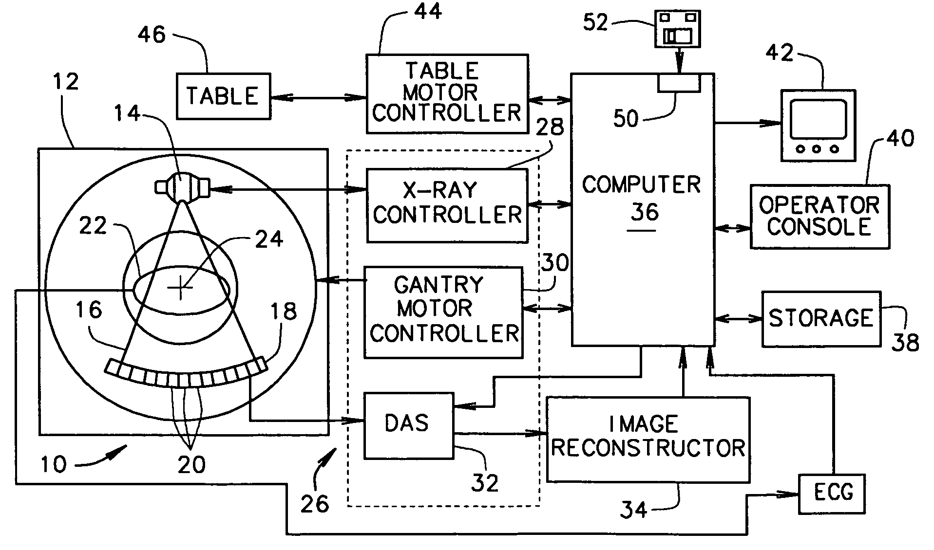
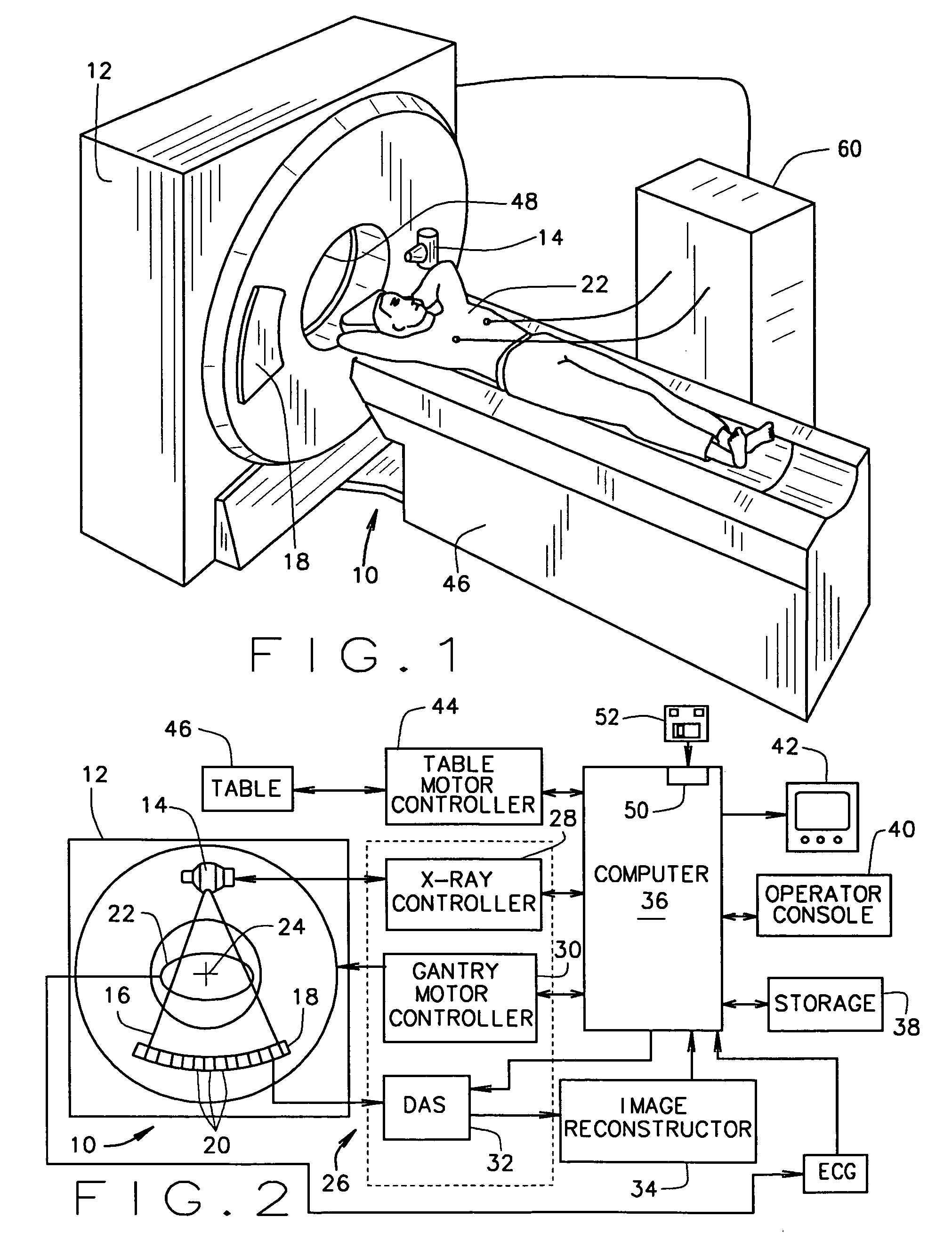
[0036] Technical effects of the present invention include, in various configurations, gating of a CT imaging system to acquire data at particular times and at particular kVps, reconstruction of images using the acquired data, and / or determination of a calcification score f...


PUM

PropertyMeasurementUnit
timeaaaaaaaaaa
velocitiesaaaaaaaaaa
speedaaaaaaaaaa

Abstract

A method for reducing mis-registration during multiple energy scanning on computed tomographic (CT) imaging systems or multiple energy electron beam tomographic (EBT) systems includes scanning a portion of a patient including a cyclically moving body part using a multiple energy computed tomographic (CT) imaging system or multiple energy electron beam tomographic (EBT) system having at least two different energies, monitoring the cyclically moving body part, and gating the multiple energy CT imaging system or multiple energy EBT system in accordance with the monitored cyclically moving body part so that acquisitions are acquired at at least two different kVps. The data acquired at the different kVps are then utilized to generate material decomposition images of the cyclically moving body part.

Description

BACKGROUND OF THE INVENTION [0001] This invention relates generally to methods and apparatus for detection and diagnosis of abnormalities related to an ischemic heart, and particularly to methods and apparatus for detecting abnormalities related to lack of adequate blood flow to myocardial tissue. However, the methods and apparatus described herein can be used for motion mitigation and material differentiation in any organ or other object, living or non-living, that can be imaged using a plurality of radiation energies and that has a predictable, periodic motion. [0002] Heart disease is the number one cause of mortality in the US. The prevalence of heart disease is also growing in the rest of the world. Most common forms of heart disease that lead to debilitating events are ischemic heart disease, which is due to abnormalities in the structure of the heart's muscle (myocardium) and valves and abnormalities of the cardiac electrical system (arrhythmias). [0003] Atherosclerotic corona...

Claims


Application Information

Patent Timeline
Patent Type & Authority Applications(United States)
IPC IPC(8): A61B6/00G01N23/00G21K1/12H05G1/60
CPCA61B6/032A61B6/4035A61B6/405A61B6/4241A61B6/482A61B6/503A61B6/504A61B6/541
Inventor JHA, SANJAY KUMARSENGUPTA, SOUMAWALTER, DEBORAH JOY
Owner GENERAL ELECTRIC CO
Why Eureka
Try Eureka