
Method and apparatus for correcting for beam hardening in CT images

a technology of computed tomography and beam hardening, applied in tomography, instruments, applications, etc., can solve the problems of detection system related image artifacts, image artifacts that are usually not free of image artifacts, and inducing beam hardening artifacts in reconstructed images

Inactive Publication Date: 2006-07-20
GENERAL ELECTRIC CO
View PDF20 Cites 52 Cited by
  • Summary
  • Abstract
  • Description
  • Claims
  • Application Information

AI Technical Summary

Problems solved by technology

However, such images are usually not free of image artifacts resulting from high-density materials.
The polychromatic nature of x-ray sources used in CT imaging systems induces beam-hardening artifacts in the reconstructed images.
To complicate this matter, detection efficiency of detector elements changes with x-ray spectrum hardened by different materials, resulting in detection system related image artifacts.
However, these calibration procedures do not correct for beam hardening problems resulting from other materials.
In addition, relative variations in detector response between detector channels is commonly induced by high-density materials, and these calibration procedures are not effective in correcting for these induced variations.
However, the correction for bone induced beam hardening is not effective to correct detector spectral response variations, which tend to create banding or center artifacts in images.
Experimental calibration with a mixture of different materials is difficult to perform.
Such calibration, were it feasible, would be complex and time consuming.

Method used


Image

  • Method and apparatus for correcting for beam hardening in CT images
  • Method and apparatus for correcting for beam hardening in CT images
  • Method and apparatus for correcting for beam hardening in CT images

Examples


Embodiment Construction

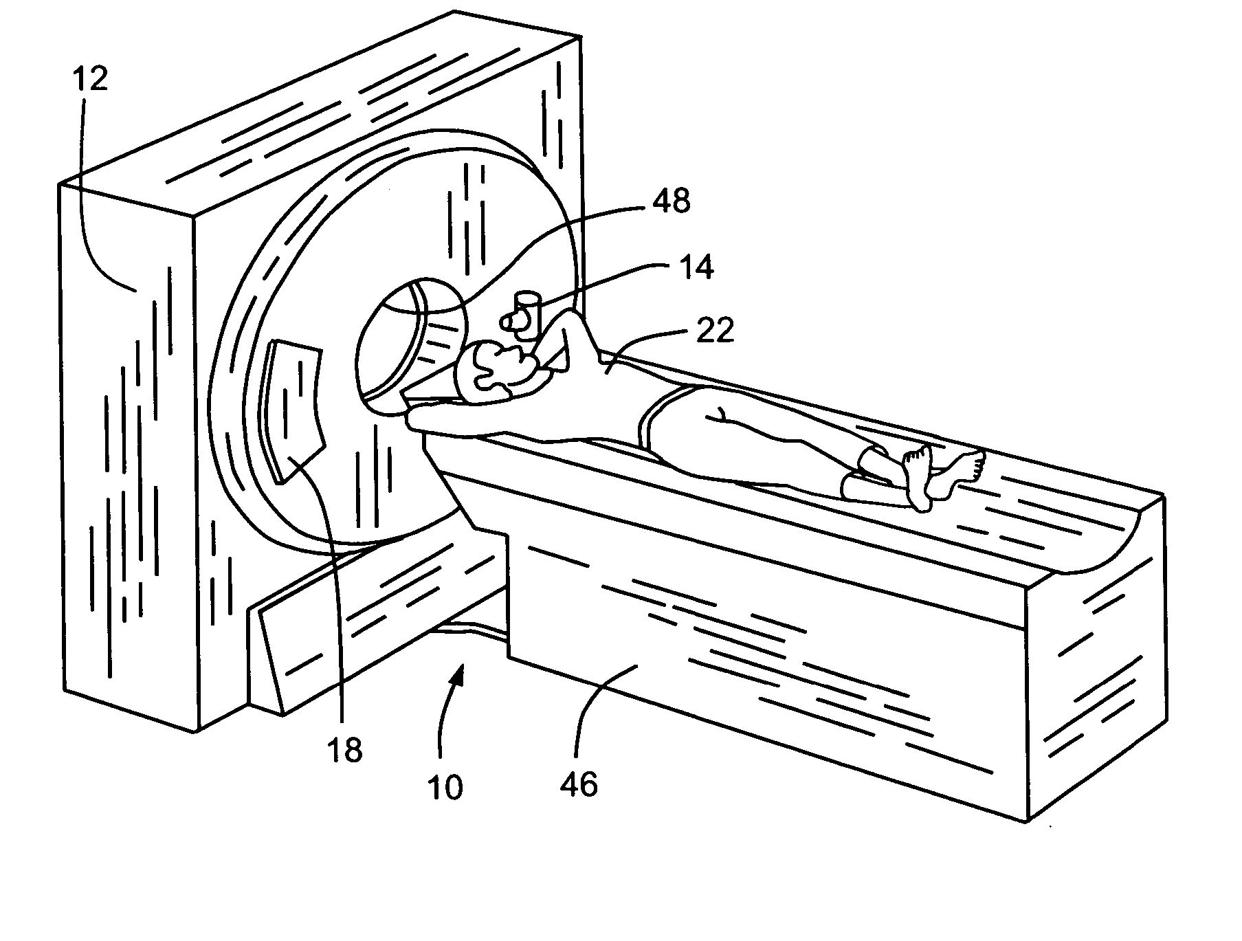
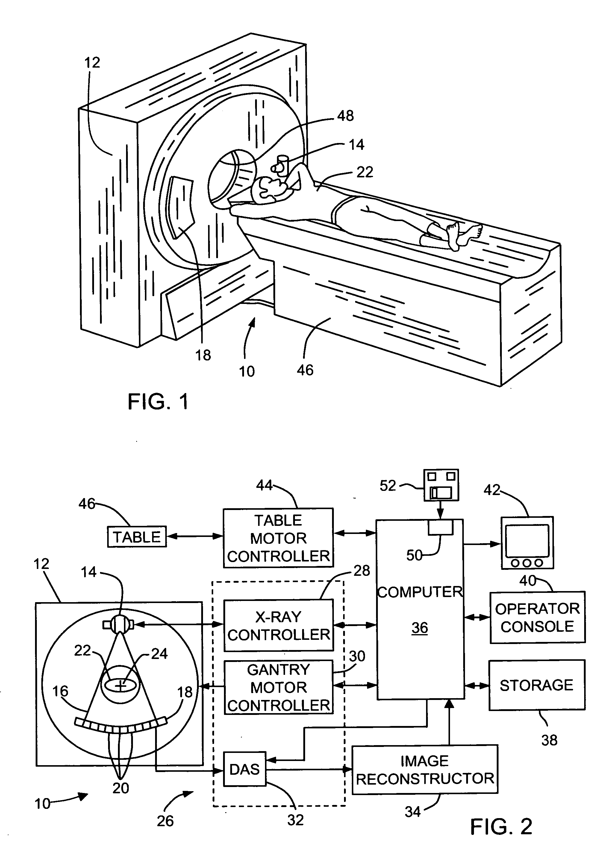
[0015] In some known CT imaging system configurations, an x-ray source projects a fan-shaped beam which is collimated to lie within an X-Y plane of a Cartesian coordinate system and generally referred to as an “imaging plane”. The x-ray beam passes through an object being imaged, such as a patient. The beam, after being attenuated by the object, impinges upon an array of radiation detectors. The intensity of the attenuated radiation beam received at the detector array is dependent upon the attenuation of an x-ray beam by the object. Each detector element of the array produces a separate electrical signal that is a measurement of the beam intensity at the detector location. The intensity measurements from all the detectors are acquired separately to produce a transmission profile.

[0016] In third generation CT systems, the x-ray source and the detector array are rotated with a gantry within the imaging plane and around the object to be imaged such that the angle at which the x-ray be...


PUM

PropertyMeasurementUnit
CTaaaaaaaaaa
CT imagingaaaaaaaaaa
thicknessesaaaaaaaaaa

Abstract

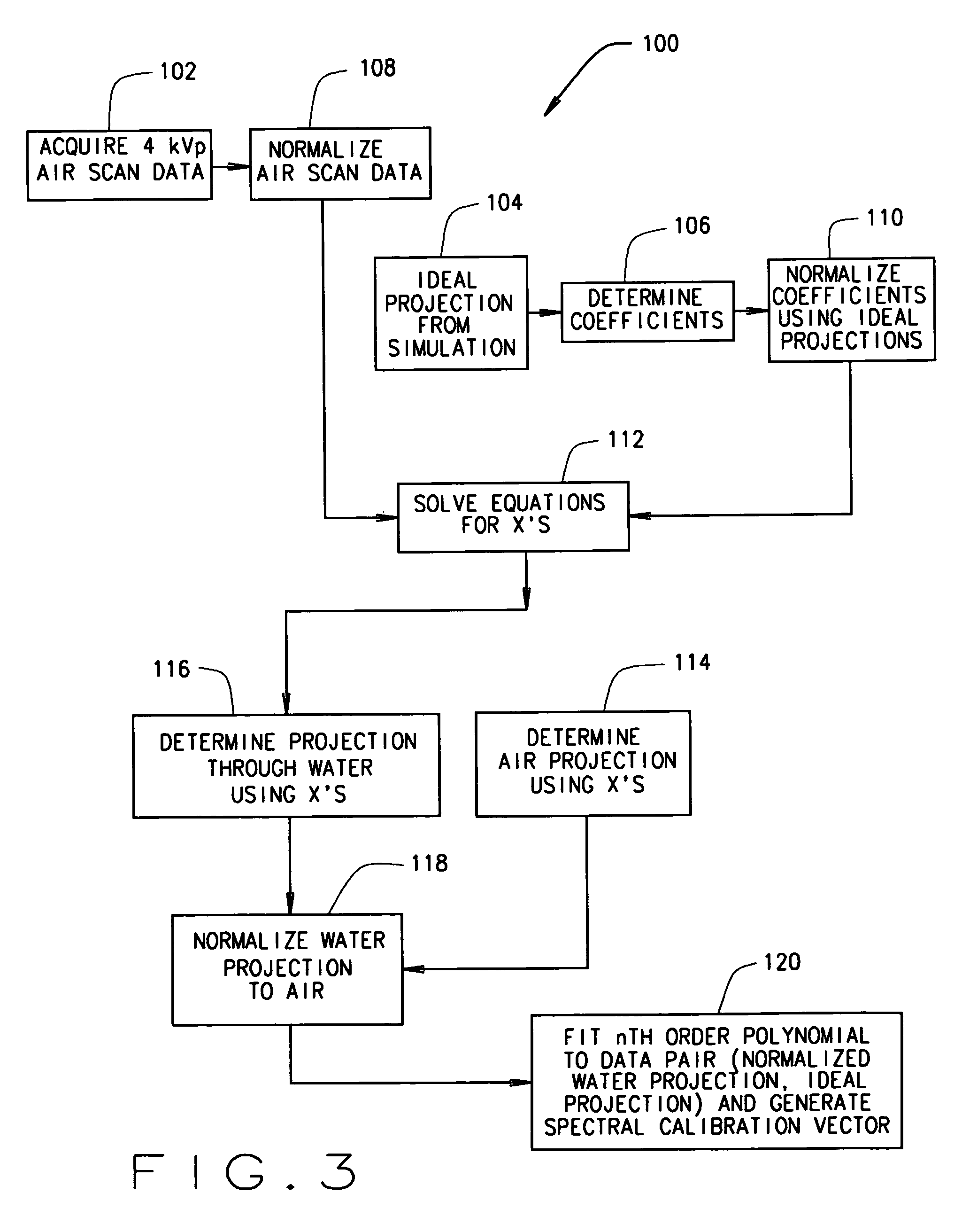
A method for determining a correction for beam hardening in CT images includes obtaining air scans at a plurality of kVp's, determining detection efficiencies for detector elements of the CT imaging apparatus, and estimating projection values through a combination of at least two different materials of different thicknesses. The method further includes determining a transfer function that translates the estimated projection values into ideal projection values for at least two of the different materials and storing the transfer function as the beam hardening correction for images of the CT imaging apparatus.

Description

BACKGROUND OF THE INVENTION [0001] This invention relates generally to computed tomographic (CT) imaging systems, and more particularly to correction of artifacts resulting from beam hardening resulting from high-density materials. [0002] It is known that in the absence of bones or other high-contrast materials, modern CT images produced from scans of patients are artifact-free, mainly due to accurate spectral calibration that removes artifacts for water or soft tissue. However, such images are usually not free of image artifacts resulting from high-density materials. [0003] Image artifacts resulting from high-density materials can be divided into several categories according to their cause. These categories include (1) beam hardening, (2) beam hardening induced detector spectral response variation, and (3) aliasing and photon starvation. Configurations of the present invention are particularly suited for correcting artifacts in the first two categories. Various configurations of th...

Claims


Application Information

Patent Timeline
Patent Type & Authority Applications(United States)
IPC IPC(8): A61B6/00H05G1/60G01N23/00G21K1/12
CPCA61B6/032A61B6/583A61B6/488A61B6/482
Inventor WU, XIAOYESIMONI, PIERO UGOTOTH, THOMAS LOUISBROMBERG, NEIL BARRY
Owner GENERAL ELECTRIC CO
Learn More