Wet type developing apparatus and wet type developing method

Active Publication Date: 2011-10-13
MIYAKOSHI PRINTING MACHINERY
View PDF10 Cites 34 Cited by
  • Summary
  • Abstract
  • Description
  • Claims
  • Application Information

AI Technical Summary

Benefits of technology

[0029]According to the preceding makeup of the invention, it is possible to separate the developing roller and the anilox roller (and also the cleaning roller if provided) in rotational contact therewith, together from the photoconductor drum simply by moving the developing unit supporting frame. This allows performing maintenance around the rollers in the developing unit at a site spaced apart from the photoconductor drum and better

Problems solved by technology

In the conventional wet type developing apparatus mentioned above, when the film thickness of the toner layer formed on the surface of the developing roller is controlled by changing the roller bias applied to the anilox roller, a small difference in electric potential between the developing roller the anilox roller to which the roller bias is applied gives rise to the problem that as the printing speed is increased or due to changes in physical property of the liquid developer, such inconveniences as a drop in image density, a deterioration in reproducibility of halftone dots, occurrence of streaks and unevenness and appearance of a trace of a cell of the surface of the anilox roller on the surface of an image, tend to be brought about, making it difficult to control so as to ensure print quality such as of print density, reproducibility of images and stability of the print quality in continuous printing.
This arrangement has the problem, however, that

Method used


Image

  • Wet type developing apparatus and wet type developing method
  • Wet type developing apparatus and wet type developing method
  • Wet type developing apparatus and wet type developing method

Examples


first embodiment

[0048]Mention is now made of the present invention with reference to FIGS. 1 to 3.

[0049]FIG. 1 is a view showing a wet type electrophotographic printing installation or machine 1 in which a plurality of (four) wet type electrophotographic printers 1a, 1b, 1c and 1d are arranged vertically parallel to one another, each of which uses a wet type developing apparatus. In the electrophotographic printing installation 1, a continuous web of paper 2 is passed first through the wet type electrophotographic printer 1a at the lowermost side and then through the electrophotographic printers 1b, 1c and 1d in turn from the lower side to the upper side to effect multi-color printing.

[0050]Since the wet type electrophotographic printers 1a-1d are identically made up, mention will be made below of makeup of the lowermost wet type electrophotographic printer 1a.

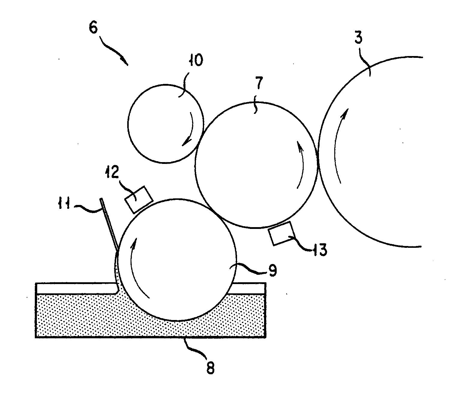
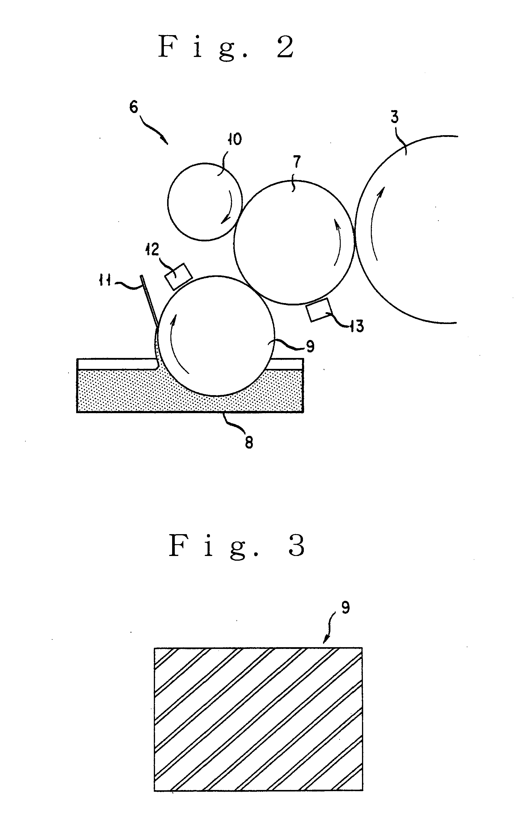
[0051]In the Figure there are shown a photoconductor drum 3, a transfer roller 4 in rotational contact with the photoconductor drum 3 and a...


PUM


Abstract

A wet type developing apparatus is provided which allows printing in a quality that is stable at an increased printing speed and also with changes in physical property of a liquid developer. The wet type developing apparatus to this end includes a liquid developer feed pathway which comprises a developing roller 7 for feeding the liquid developer onto a photoconductor drum 3; an anilox roller 9 immersed in part in the liquid developer and driven to rotate in rotational contact with the developing roller; and a doctor blade 11 disposed in contact with a surface of the anilox roller for controlling the rate of drawing up of the liquid developer. The developing and anilox rollers have their peripheral surfaces moving in an identical direction and at an identical rate of movement in an area of their rotational contact. A toner charger 12 is disposed opposite to a surface of the anilox roller downstream of an area of contact of the doctor blade with the anilox roller and upstream of an area of rotational contact of the anilox roller with the developing roller in a rotation direction of the anilox roller.

Description

TECHNICAL FIELD[0001]The present invention relates to a wet type developing apparatus for use in a wet type electrophotographic printer, in which an electrostatic latent image formed on a photoconductor drum is developed (or visualized) with a liquid developer, and to a wet type developing method for use with the apparatus.BACKGROUND ART[0002]In the wet type developing apparatus, an anilox roller (feed roller) immersed in part in a liquid developer is driven to rotate in rotational contact with a developing roller with which the photoconductor drum is driven to rotate in rotational contact, and the liquid developer is fed onto the developing roller via the anilox roller. With the developing roller driven to rotate in rotational contact with a photoconductor drum, an electrostatic latent image formed on the photoconductor drum is developed into a toner image. And, the toner image developed on the photoconductor drum is transferred onto a web of paper (recording medium).[0003]In a con...

Claims


Application Information

Patent Timeline
IPC IPC(8): G03G15/10
CPCG03G15/104
Inventor IZAWA, HIDEOSETOYAMA, JUNICHINAMIKI, TAKAOMERA, SUMITO
Owner MIYAKOSHI PRINTING MACHINERY
Why Eureka
Try Eureka