
Steering assist device

a technology of steering assist and steering load, which is applied in the direction of steering initiation, instruments, vessel construction, etc., can solve the problems of affecting the operation of the steering device, so as to achieve the effect of less steering load, increased auxiliary torque, and appropriate reduction of steering load

Active Publication Date: 2011-10-13
TOYOTA JIDOSHA KK
View PDF11 Cites 61 Cited by
  • Summary
  • Abstract
  • Description
  • Claims
  • Application Information

AI Technical Summary

Benefits of technology

[0022]According to the first aspect, a steering load on a driver can be appropriately reduced. Specifically, according to the first aspect, when it is determined that the vehicle is performing lane change, the control of the auxiliary torque to bring the position of the traveling vehicle close to the center line of the travel lane is suppressed, and only the control of the auxiliary torque to cause the vehicle to perform turning in accordance with the curvature of the lane is executed. Therefore, when the driver tries to intentionally leave the current travel lane, such as when the driver tries to perform lane change, generation of an auxiliary torque that brings the vehicle back to the center line of the travel lane is suppressed. On the other hand, an auxiliary torque required for curve traveling or the like is continuously generated before, during, and after the lane change. Accordingly, the driver can drive the vehicle comfortably with less steering load.
[0023]According to the second aspect, the auxiliary torque can be appropriately controlled based on the shape of the travel lane, and the relative position of the vehicle to the center line of the travel lane.
[0024]According to the third aspect, while the vehicle is performing lane change, the control by the second torque control section is suppressed only when the direction in which the auxiliary torque controlled by the second torque control section acts is different from the direction of the lane change of the vehicle. In other words, even when the vehicle is performing lane change, the control by the second torque control section is executed as usual so long as the direction in which the auxiliary torque controlled by the second torque control section acts is the same as the direction of the lane change of the vehicle. That is, the control by the second torque control section to increase the auxiliary torque is possible for the direction of the auxiliary torque intended by the driver. Accordingly, for example, if the vehicle is moved to a direction not intended by the driver due to a disturbance such as lateral wind, the auxiliary torque can be increased in the direction intended by the driver by using the second torque control section as well as the first torque control section. Therefore, the driver can perform a steering operation in his / her intended direction with smaller steering load as compared to the case where the control by the second torque control section is suppressed.
[0025]According to the fourth aspect, whether or not the vehicle is performing lane change can be determined by a simple process in accordance with whether or not the direction indicator is being operated.
[0026]According to the fifth aspect, whether or not the vehicle is performing lane change can be determined by a simple process in accordance with the magnitude of the steering torque.
[0027]According to the sixth aspect, the steering torque threshold value can be set to an appropriate value in accordance with the curvature of the travel lane. Accordingly, whether or not the vehicle is performing lane change can be accurately determined.

Problems solved by technology

In the control process by the conventional steering assist device, however, generation of an auxiliary torque might be halted even in a situation where the driver needs an auxiliary torque.
Such a sudden halt of generation of the auxiliary torque might cause a rapid increase in the steering load on the driver.
In this case, such an increase in the steering load might cause the driver to feel stress.

Method used


Image

  • Steering assist device
  • Steering assist device
  • Steering assist device

Examples


first embodiment

[0045]The following will describe a steering assist device 1 according to a first embodiment of the present invention. The steering assist device 1 is a device for assisting a steering force of a driver. The first embodiment will describe an example where the steering assist device 1 is mounted on a vehicle 100.

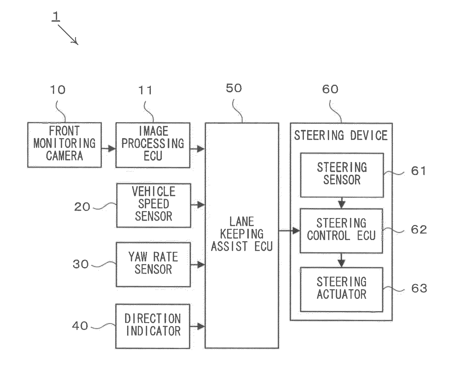
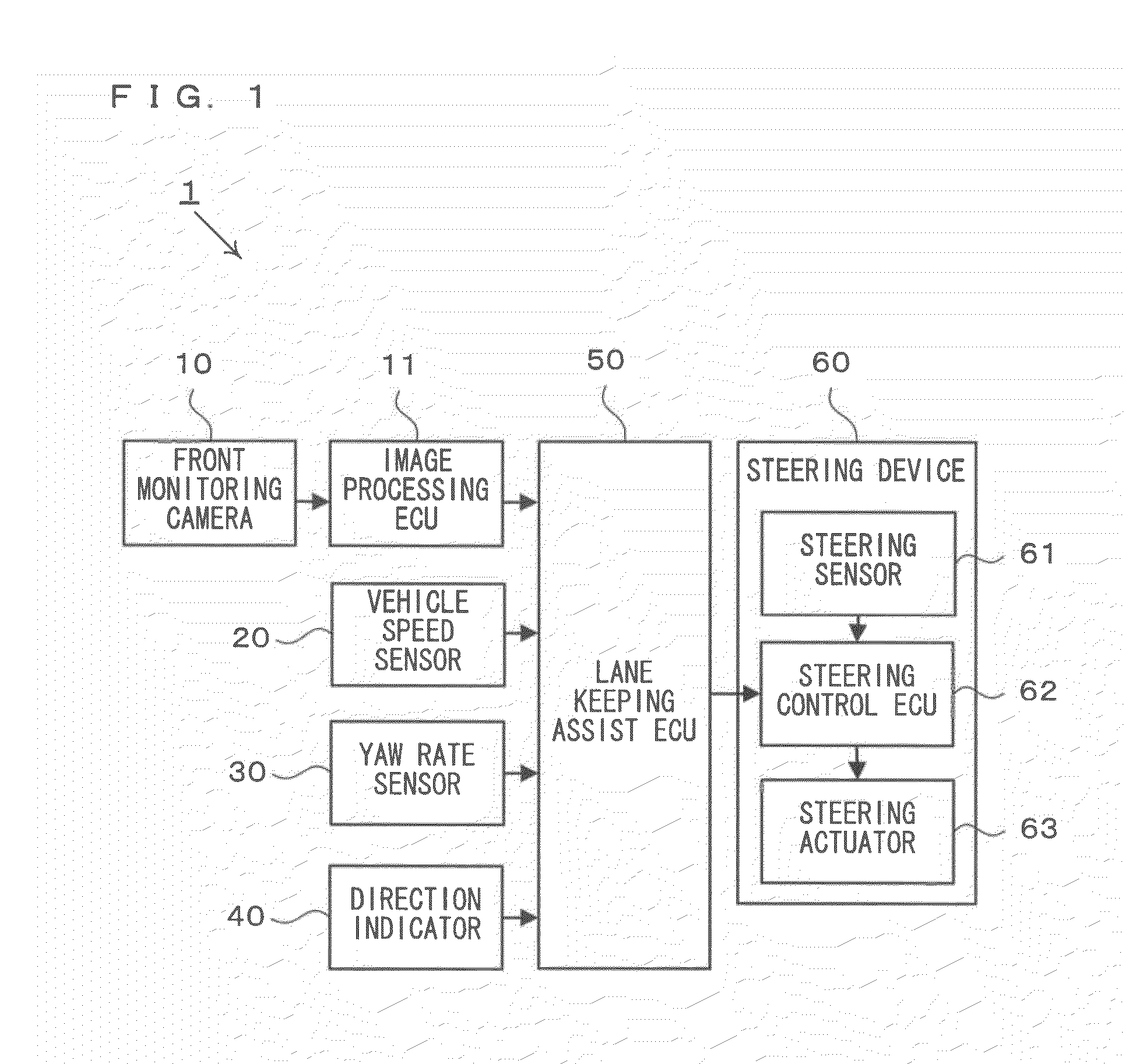
[0046]First of all, the configuration of the steering assist device will be described with reference to FIG. 1. FIG. 1 is an example of a block diagram illustrating the configuration of the steering assist device according to the first embodiment. As shown in FIG. 1, the steering assist device is provided with a front monitoring camera 10, an image processing ECU 11, a vehicle speed sensor 20, a yaw rate sensor 30, a direction indicator 40, a lane keeping assist ECU 50, and a steering device 60.

[0047]The front monitoring camera 10 is a device for taking an image in front of the vehicle 100 (referred to as a front image, hereinafter). The front monitoring camera 10 is typicall...

second embodiment

[0075]In the above-described first embodiment, whenever the vehicle 100 is performing lane change, the lane keeping assist ECU 50 always halts the control of the auxiliary torque TA by the feed-back control. However, the lane keeping assist ECU 50 may halt the feed-back control only when the vehicle 100 is performing lane change and it is determined that the auxiliary torque by the feed-back control interferes with the driver's operation. Specifically, the lane keeping assist ECU 50 determines that the auxiliary torque by the feed-back control interferes with the driver's operation when the direction in which the vehicle 100 turns due to the auxiliary torque by the feed-back control, i.e., the direction in which the FB control acceleration Gfb acts, is different from the direction of lane change of the vehicle 100.

[0076]Hereinafter, a steering assist device according to a second embodiment will be described. The configuration of the steering assist device according to the second emb...

third embodiment

[0089]In the above-described first and second embodiments, the lane keeping assist ECU 50 halts the feed-back control while the vehicle 100 is performing lane change. However, the lane keeping assist ECU 50 may perform control for suppressing the feed-back control without completely halting the feed-back control. Specifically, the lane keeping assist ECU 50 may suppress the feed-back control by controlling a gain value kD and a gain value kθ relating to the feed-back control.

[0090]The following will describe a steering assist device according to a third embodiment. The configuration of the steering assist device of the third embodiment is identical to that of the first embodiment except the process executed by the lane keeping assist ECU 50. Therefore, detailed description of the configuration will be omitted.

[0091]FIG. 9 is an example of a flowchart illustrating the details of the process executed by the lane keeping assist ECU 50 of the third embodiment. The lane keeping assist EC...


PUM


Abstract

A steering assist device capable of appropriately reducing a steering load on a driver is provided. A steering assist device for assisting a steering operation of a driver who drives a vehicle, comprises: an auxiliary torque generation section for causing a steering device of the vehicle to generate an auxiliary torque that assists a steering force of the driver; a first torque control section for controlling the auxiliary torque so as to cause the vehicle to perform turning in accordance with a curvature of a travel lane in which the vehicle travels; a second torque control section for controlling the auxiliary torque so as to bring the position of the vehicle close to a center line of the travel lane; a lane change determination section for determining whether or not the vehicle is performing lane change; and a control suppression section for suppressing the control of the auxiliary torque by the second torque control section when it is determined that the vehicle is performing lane change.

Description

TECHNICAL FIELD[0001]The present invention relates to a steering assist device and, more particularly, to a steering assist device for assisting a steering force of a driver of a vehicle.BACKGROUND ART[0002]Conventionally, in order to reduce burden on drivers driving vehicles, steering assist devices have been developed, each of which gives, to a steering, an auxiliary torque for assisting a steering force of a driver in accordance with a traveling state of a vehicle. As a type of such steering assist devices, a steering assist device has been developed, which gives, to a steering, an auxiliary torque so as to keep the position of a vehicle in a lane in which the vehicle travels. This steering assist device is known as a so-called LKA System (Lane Keeping Assist System).[0003]An example of the above-described steering assist devices is disclosed in Patent Literature 1. A steering control device disclosed in Patent Literature 1 calculates a lateral target acceleration of a vehicle, w...

Claims


Application Information

Patent Timeline
IPC IPC(8): B62D6/08
CPCB62D15/025
Inventor KATAOKA, HIROAKI
Owner TOYOTA JIDOSHA KK
Learn More