Traction Control Device

a technology of traction control and control device, which is applied in the direction of braking system, process and machine control, instruments, etc., can solve the problem that the driving torque cannot be transmitted to the other driving wheels, and achieve the effect of preventing acceleration reduction

Active Publication Date: 2011-10-13
KOMATSU LTD
View PDF19 Cites 21 Cited by
  • Summary
  • Abstract
  • Description
  • Claims
  • Application Information

AI Technical Summary

Benefits of technology

[0007]On a soft road, travel resistance is significantly changed due to sinking of the wheel or wheels into the road surface, so that the acceleration during travelling tends to be reduced under the influence of the travel resistance irrespective of the occurrence of an error in the estimation of the vehicle speed or a friction coefficient against the road surface. Thus, a slip ratio for a soft road is set high as compared with one for any other road surface so that soil or the like is dug out of the road surface, thereby reducing the travel resistance and consequently improving the acceleration. A conventional TCS device, however, sets the target slip ratio in consideration of not only a soft road but also any other road surface, so that it is difficult to prevent a reduction in the acceleration in the latter case.
[0010]With the above arrangement, when the target brake torques to the wheels reach or exceed the pre-stored threshold, the traction control device reduces the target brake torques. Specifically, when the target brake torques reach a certain level, the traction control device simultaneously reduces the brake torques to the wheels. Since the brake torques applied to the wheels during the TCS control are reduced, it is possible to prevent a reduction in a driving force resulting from excessive application of brake. Thus, the driving force to each wheel can be increased if necessary, thereby preventing a reduction in the acceleration during travelling.
[0011]Further, in the traction control device of the above aspect, the target brake torques to the wheels are reduced in accordance with the difference between the target brake torque to the reference wheel and the pre-stored threshold. As a result, since the target brake torques to the wheels depend on the target brake torque to the reference wheel, a common reference to determine a torque reduction amount is used for the wheels. Since the target brake torques to the wheels are determined in accordance with the difference relative to the threshold, the target brake torques are prevented from being discontinuous before and after the reduction of the torques. Thus, it is possible to prevent a large variation in the reduction amounts of the target brake torques to the wheels and a discontinuous change in the target brake torques before and after the reduction of the torques. As a result, the brake torques to the wheels can be similarly and smoothly changed, thereby preventing a large abrupt change in the driving force to each wheel or an excessive increase in the driving force to each wheel relative to the other wheels. Consequently, a reduction in the acceleration can be prevented without annoying the driver.
[0013]With the above arrangement, the traction control device selects one of the wheels having the smallest target brake torque as the reference wheel. Thus, the difference between the target brake torque to the reference wheel and the threshold is calculated from the smallest value of the target brake torques to the wheels and the threshold. Specifically, such a difference, which is used as a reference to determine the reduction amount of the target brake torques, is set within a range of possible target brake torque values of the wheel that has the smallest target brake torque (i.e., the wheel that is smaller in slip amount than any other wheel and is stable relative to the road surface), and consequently, never exceeds the target brake torque value of this wheel. As a result, the brake torques to the wheels can be prevented from being unnecessarily reduced. Thus, while the travelling stability and course traceability of the construction machine are ensured at the time of the occurrence of a slip, a reduction in acceleration can be prevented.
[0016]With the above arrangement, the traction control device determines whether or not the target brake torques to both front wheels reach or exceed the front-wheel threshold and whether or not the target brake torques to both rear wheels reach or exceed the rear-wheel threshold. When the reference wheel is one of the front wheels, the traction control device reduces the target brake torques in accordance with the difference between the target brake torque to the reference wheel and the front-wheel threshold. When the reference wheel is one of the rear wheels, the traction control device reduces the target brake torques in accordance with the difference between the target brake torque to the reference wheel and the rear-wheel threshold. Thus, with the traction control device, even when the braking mechanisms used for the front wheels and the braking mechanisms used for the rear wheels have different characteristics, a timing for starting the reduction of the target brake torques and the torque reduction amount can be set in accordance with the characteristics of the braking mechanisms by changing the front-wheel threshold and the rear-wheel threshold. As a result, a reduction in the acceleration can be more effectively prevented.
[0018]With the above arrangement, the respective traction forces between the wheels and the road surface are estimated and then the estimated traction forces are used to calculate the target brake torques to the wheels, so that it is possible to calculate values of target brake torque suitable for the road surface. Thus, a reduction in the acceleration can be prevented, thereby maintaining the acceleration at a level suitable for the road surface.

Problems solved by technology

However, on a soft ground such as a mine or a construction site, since positional differences between the wheels lead to different friction coefficients between the wheels and the road surface, even the construction machines suffer from the slip of part of the driving wheels, so that a driving torque cannot be transmitted to the other driving wheels.
In such a case, most of engine output is used to drive the slipping driving wheel or wheels, so that a sufficient amount of the driving force cannot be transmitted to the road surface, thereby reducing acceleration.

Method used


Image

  • Traction Control Device
  • Traction Control Device
  • Traction Control Device

Examples


Embodiment Construction

)

[0031]Exemplary embodiment(s) of the invention will be described below with reference to the attached drawings.

1. Structure of Dump Truck 1

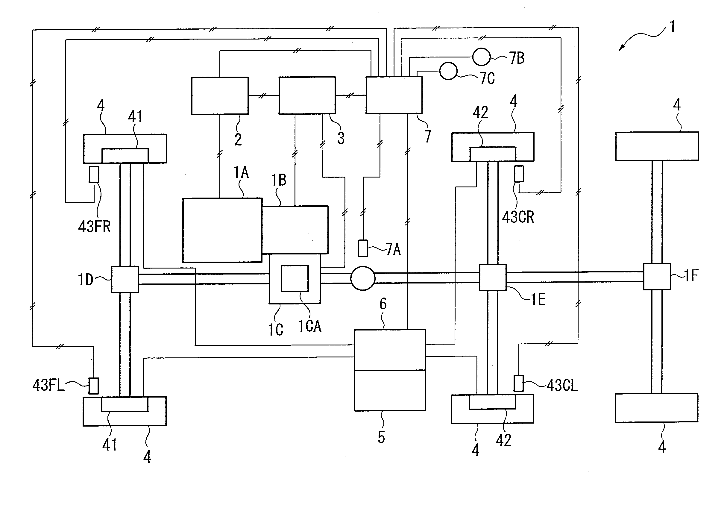
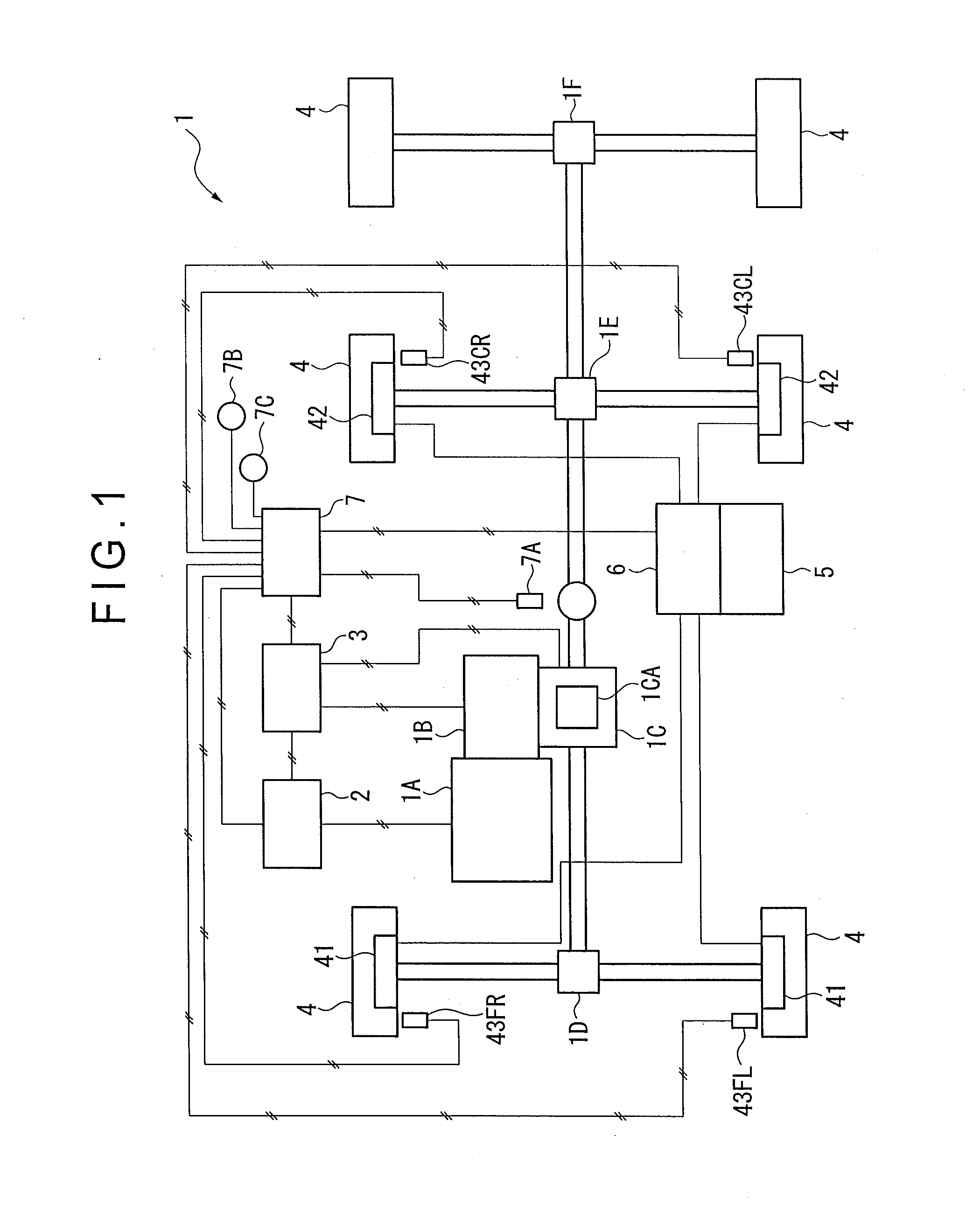
[0032]FIG. 1 shows a dump truck 1 according to an exemplary embodiment of the invention. The dump truck 1 is an articulated truck that includes separate front and rear vehicle body frames. A vehicle body of the dump truck 1 includes an engine 1A, a transmission 1B, differential mechanisms 1C to 1F and a differential adjusting mechanism 1CA. The output of the engine 1A is controlled by an engine controller 2 and is transmitted to the transmission 1B. The transmission 1B includes a torque converter and a lockup mechanism (not shown). A transmission controller 3 performs speed change control and lockup control on the transmission 1B.

[0033]A rotary driving force transmitted from the engine 1A to the transmission 1B rotates all wheels 4 via the differential mechanisms 1C to 1F and is transmitted to the road surface.

[0034]In this exemplary embodiment,...


PUM


Abstract

The invention provides a traction control device capable of preventing a reduction in acceleration. A fraction control device of the invention includes a braking mechanism controller that controls a braking mechanism. The braking mechanism controller includes: a target brake torque calculating section that calculates a target brake torque to each of wheels based on the rotation speed of the wheel and an estimated vehicle speed; a target brake torque determining section that determines whether or not the target brake torque reaches or exceeds a per-stored threshold; a reference wheel determining section that selects a reference wheel used as a reference for controlling the braking mechanism based on the target brake torque to each of the wheels; and a target brake torque reducing section that reduces the target brake torque in accordance with a difference between the target brake torque to the reference wheel and the threshold when the target brake torque to one of the wheels reaches or exceeds the threshold.

Description

TECHNICAL FIELD[0001]The present invention relates to a control device for controlling a driving force of a travelling vehicle. In particular, the present invention relates to a traction control device of a construction machine capable of controlling a braking mechanism provided to each wheel.BACKGROUND ART[0002]Construction machines are frequently used by its nature in a place whose road surface is in a bad condition as compared with general vehicles. However, on a soft ground such as a mine or a construction site, since positional differences between the wheels lead to different friction coefficients between the wheels and the road surface, even the construction machines suffer from the slip of part of the driving wheels, so that a driving torque cannot be transmitted to the other driving wheels. In such a case, most of engine output is used to drive the slipping driving wheel or wheels, so that a sufficient amount of the driving force cannot be transmitted to the road surface, th...

Claims


Application Information

Patent Timeline
Patent Type & Authority Applications(United States)
IPC IPC(8): B60T8/175B60W10/12B60W10/18B60W30/18
CPCB60K17/35B60W2720/406B60T8/4809B60T10/00B60T2201/14B60T2210/16B60W10/14B60W10/184B60W30/18172B60W2520/263B60W2520/266B60W2520/28B60W10/16B60W2300/17B60W2510/0233B60W2720/403B60T8/175
Inventor UEMATSU, KOJIHATAKE, KAZUHIROKUSUMOTO, YUYA
Owner KOMATSU LTD
Why Eureka
Try Eureka