Printing relief plate
a relief plate and printing technology, applied in the field of printing relief plates, can solve the problems of high dot gain and graininess, different printed areas tend to exhibit different printing densities, and different printing densities, so as to reduce printing pressure instabilities, reduce printing defects, and avoid localized enlargement of small halftone dots
- Summary
- Abstract
- Description
- Claims
- Application Information
AI Technical Summary
Benefits of technology
Problems solved by technology
Method used
Image
Examples
first embodiment
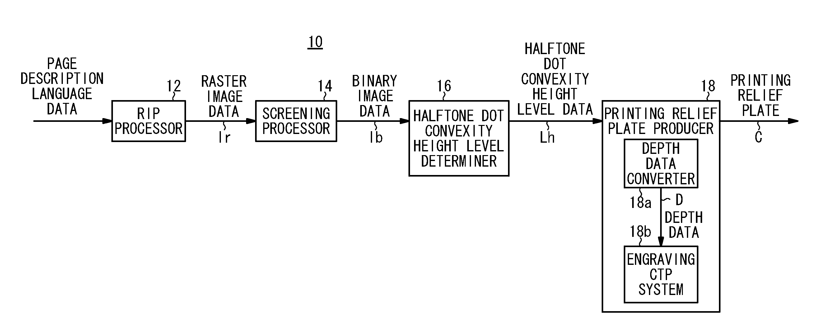
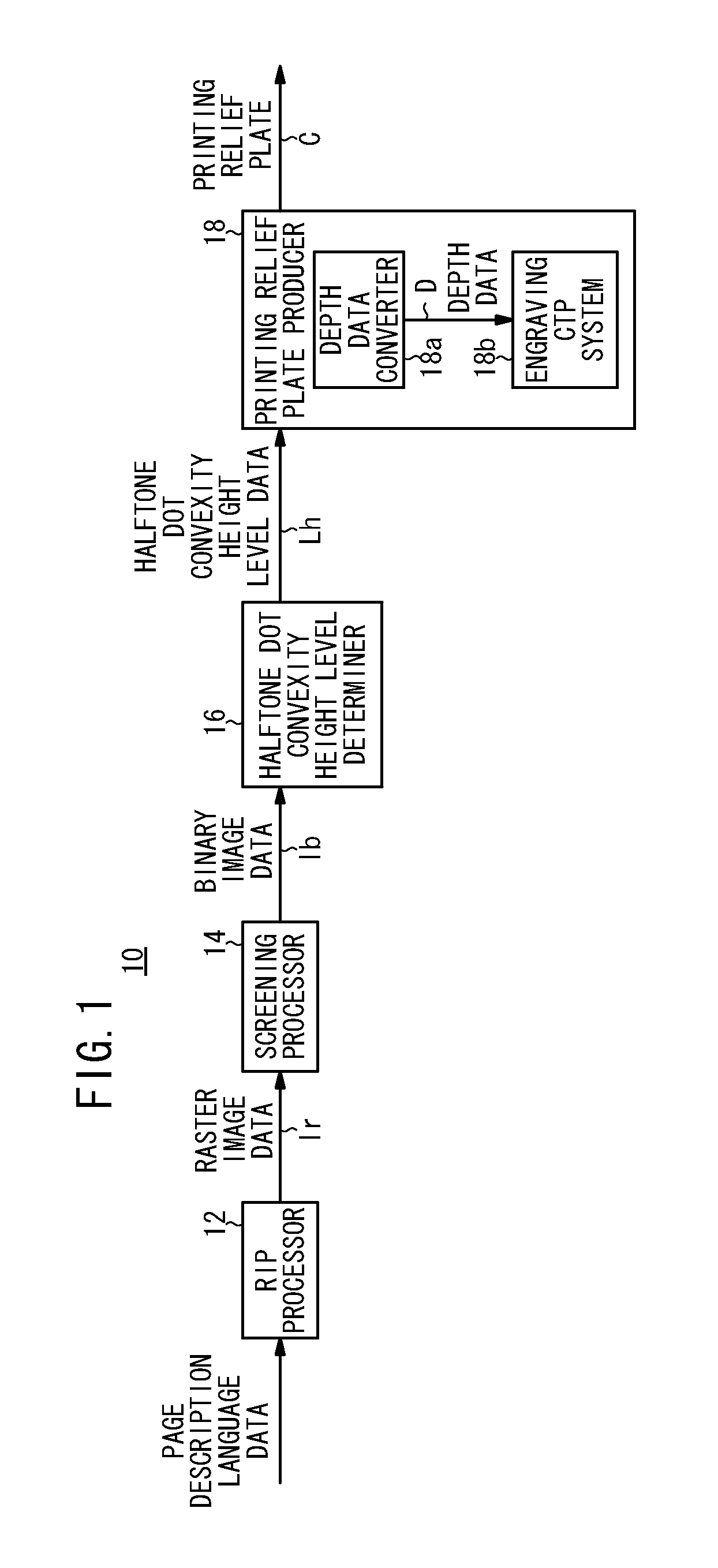
[0088]In the first embodiment, as noted above, one halftone dot block Hbr is formed from four halftone dot cells Hc of a 2×2 array (see FIG. 5). The halftone dot cells Hc are made up from two types of halftone dot cells (one first halftone dot cell HcI, and three second halftone dot cells HCII), in which levels (a plurality of levels) of heights of the printing surfaces of the halftone dot convexities 204, which are formed corresponding to positions of the respective halftone dot cells Hc, differ from one another, the halftone dot area ratio Har being of a fixed value, for example, a value of 10% or less, corresponding to the highlight gradation.
[0089]Stated otherwise, with the halftone dot block Hbr in the example of FIG. 5, which is constructed from 2×2 halftone dot cells Hc, one halftone dot block Hbr is made up from one first halftone dot cell HcI, which is arranged at the lower right, and three second halftone dot cells HcII, which are arranged at the upper right, upper left, a...
second embodiment
[0117]In place of the example of FIG. 9, as shown in the print Pa′ of FIG. 10, the image of the screen tint region Aa′ in which the halftone dot area ratio Har is of the same percentage, as described with reference to the printing relief plate C of FIG. 3, may be constituted by a regular arrangement made up from main halftone dots 214m, which are printed by the main halftone dot convexities 204m having the halftone dot height level Lh1 of which the height thereof is of the highest level, halftone dots 214s, which are printed by the halftone dot convexities 204s having the halftone dot height levels Lh2 of which the height thereof is of the next highest level, and halftone dots 214t, which are printed by the halftone dot convexities 204t having the halftone dot height levels Lh3 of which the height thereof is of the lowest level.
[0118]In the example of FIG. 10, the screen tint region of the printing relief plate C is defined by a repeated arrangement of sections (regions) of halftone...
third embodiment
[0119]Next, an example of processing of the halftone dot convexity height level data Lh, which is performed by the halftone dot convexity height level determiner 16 when halftone dot cells (first halftone dot cells HcI, second halftone dot cells HcII, and third halftone dot cells HcIII) that differ in height are used, shall be described below in detail.
[0120]FIG. 12A shows an arrangement pattern of a halftone dot block Hbrb made up from sixteen halftone dot cells Hc (first through third halftone dot cells HcI, HcII, and HcIII) arranged in a 4×4 array.
[0121]FIG. 12B shows schematically a basic pattern (generalized expression) of a printing relief plate Cab making up a screen tint region Ab having the same halftone dot area ratio Har, which is formed corresponding to the halftone dot block Hbrb shown in FIG. 12A. The square shaped portion surrounded by the broken line also is referred to as a halftone dot block Hbrb.
[0122]Referring to the halftone dot blocks Hbrb of FIGS. 12A and 12B,...
PUM
 Abstract
Description
Claims
Application Information
 - R&D
- Intellectual Property
- Life Sciences
- Materials
- Tech Scout
- Unparalleled Data Quality
- Higher Quality Content
- 60% Fewer Hallucinations
Browse by: Latest US Patents, China's latest patents, Technical Efficacy Thesaurus, Application Domain, Technology Topic, Popular Technical Reports.
© 2025 PatSnap. All rights reserved.Legal|Privacy policy|Modern Slavery Act Transparency Statement|Sitemap|About US| Contact US: help@patsnap.com


