Sewing machine

a sewing machine and guide technology, applied in the field of sewing machines, can solve the problem that the operation of pulling out the sewing material from the guide prior to the sewing start is unnecessary

Active Publication Date: 2011-10-20
TOKAI IND SEWING MACH CO LTD
View PDF10 Cites 3 Cited by
  • Summary
  • Abstract
  • Description
  • Claims
  • Application Information

AI Technical Summary

Benefits of technology

[0011]In view of the foregoing, it is an object of the present invention to provide an improved sewing machine which does not require time and labor for cutt...

Problems solved by technology

As a consequence, operation for pulling out the sewing mater...

Method used


Image

  • Sewing machine
  • Sewing machine
  • Sewing machine

Examples


first embodiment

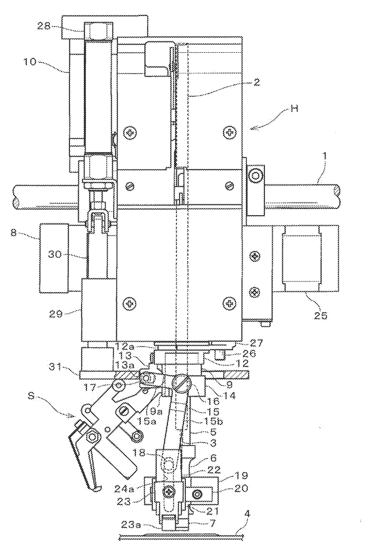
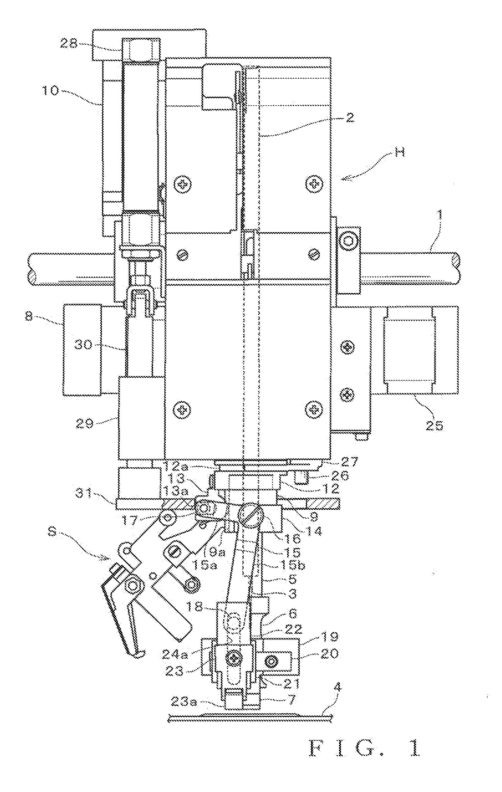
[0031]FIG. 1 is explanatory of a general construction of a sewing machine to which are applied basic principles of the present invention; more specifically, FIG. 1 is a front view of a machine head H of the sewing machine. Whereas the embodiment can be constructed as a multi-head sewing machine having a plurality of machine heads H, only one machine head H is shown to facilitate understanding of the illustration and following description. FIG. 2 is a left side view of the machine head H shown in FIG. 1. The machine head H operates to sew an elongated sewing material (such as a tape or cord), wound on a not-shown bobbin, onto a sewing workpiece (such as a fabric). Main machine shaft 1 extends through the machine head H. A needle bar 2 is reciprocatively driven vertically or in an up-down direction, together with a sewing needle 3 fixed to the lower end thereof, by means of a not-shown needle bar drive mechanism. Lock stitching is performed in the well-known manner through the up-and-...

second embodiment

[0079]The slip plate 31 is lowered in the state of FIGS. 10 and 11 and the base member 34′ is caused to pivot about the second lever pin 35 in the clockwise direction of FIG. 10 so that it moves from the evacuation position of FIG. 10 toward the cutting position of FIG. 13. While the base member 34′ is in the evacuation position, as shown in FIG. 10, the knife base 40′ is held in the pivoting position of FIG. 10 by the biasing force of the second coil spring 46, and the driver lever 51 having the roller 43 of the knife base 40′ fitted in the U-shaped fitting portion 51c is also held in the pivoting position of FIG. 10. Once the base member 34′ pivots from the position of FIG. 10 to a pivoting position of FIG. 12, the roller 53 provided on the drive lever 51 abuts against the lower surface of the slip plate 31. As the base member 34′ pivots to the pivoting position of FIG. 12, the distal end portion of the thread hook member 54 passes the neighborhood of the needle drop position and ...


PUM


Abstract

A guide is mounted to a rotary member which is freely rotatable about the axis of a needle bar, and guides a sewing material to a needle drop position of the sewing needle. A cutter device is mounted to a side of the rotary member opposed to the guide in such a manner that the cutter device is rotatable together with the rotary member for cutting the sewing material, having been paid out from the guide, at a predetermined cutting position. A retention mechanism is incorporated in the cutter device for retaining an end portion of the sewing material, at a position closer to the guide than the predetermined cutting position and in interlocked relation to cutting, by the cutter device, of the sewing material. Thus, upon restart of sewing of the sewing material, the retention mechanism retains an end portion of the sewing material.

Description

BACKGROUND[0001]The present invention relates generally to sewing machines of a type which sews an elongated sewing material, such as a tape or cord, onto a sewing workpiece, such as a fabric, through lock stitching.[0002]Heretofore, there have been known sewing machines of a type which includes a vertically driven needle bar, a sewing needle fixed to the lower end of the needle bar, a rotary member mounted concentrically with the needle bar and freely rotatable about the axis of the needle bar, and a guide fixed to the rotary member for guiding an elongated sewing material to a needle drop position of the sewing needle. The sewing machines of this type operate to sew the sewing material onto a sewing workpiece (fabric) through lock stitching while controlling the rotation of the rotary member in accordance with a moving direction of the fabric based on embroidery data and appropriately adjusting the orientation of the guide to optimize the direction in which the sewing material is ...

Claims


Application Information

Patent Timeline
IPC IPC(8): D05B35/06D05C7/08D05B37/04
CPCD05B35/06D05C7/08D05B37/04
Inventor KONDOU, TETSUROU
Owner TOKAI IND SEWING MACH CO LTD
Why Eureka
Try Eureka