
Supporting pillar for an aircraft's structural component manufactured by a selective laser melting process

a technology of laser melting process and supporting pillar, which is applied in the direction of aircraft crew accommodation, machine supports, other domestic articles, etc., can solve the problems of buckling and the tendency of the hollow body to buckle, and the need for a greater bending force at this position

Inactive Publication Date: 2011-10-20
AIRBUS OPERATIONS GMBH
View PDF2 Cites 11 Cited by
  • Summary
  • Abstract
  • Description
  • Claims
  • Application Information

AI Technical Summary

Benefits of technology

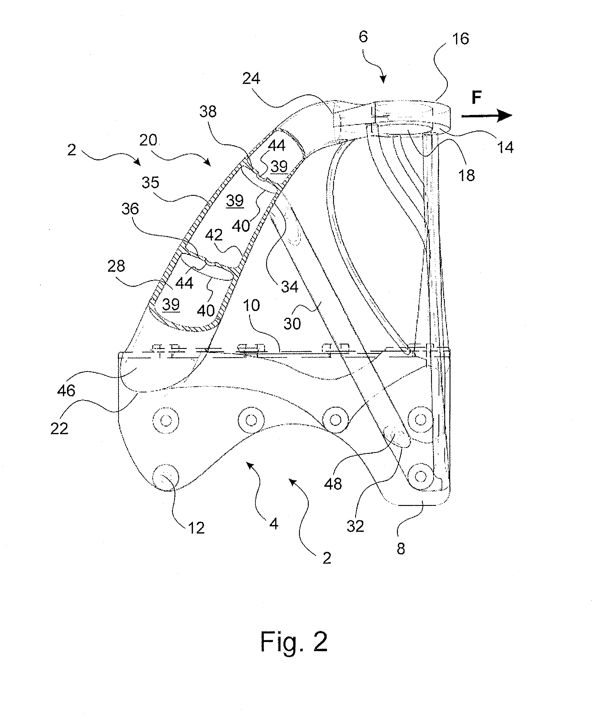
[0006]According to one aspect of the present invention, an elongated supporting pillar for a high-strength structural component is designed to absorb bending forces that act transversely to a longitudinal direction of the supporting pillar. The supporting pillar comprises a wall which at least in some regions encloses an elongated cavity of the supporting pillar. A reinforcement structure is arranged within the cavity and transversely to the direction of longitudinal extension in such a manner that the reinforcement structure improves flexural rigidity. The reinforcement structure is formed integrally, i.e. in a single piece, with the wall, wherein both the wall and the reinforcement structure are formed with a meltable material.
[0008]With the use of meltable material it is possible to produce the supporting pillar with layers that are built one on top of the other and that are interconnected, as will be described later in the context of a production method according to the invention. To this effect any meltable material is suitable, for example plastic or metal.

Problems solved by technology

If elongated hollow bodies enclosed by a wall, for example tubular structures, are subjected to bending forces, these hollow bodies tend to buckle.
Arranging a reinforcement structure within the cavity at the potential buckling position results in a greater bending force having to be applied at this position for buckling to occur.

Method used


Image

  • Supporting pillar for an aircraft's structural component manufactured by a selective laser melting process
  • Supporting pillar for an aircraft's structural component manufactured by a selective laser melting process
  • Supporting pillar for an aircraft's structural component manufactured by a selective laser melting process

Examples


Embodiment Construction

[0028]It should be mentioned that identical components in the figures have the same reference characters, and that the drawings are merely diagrammatic and not necessarily true to scale.

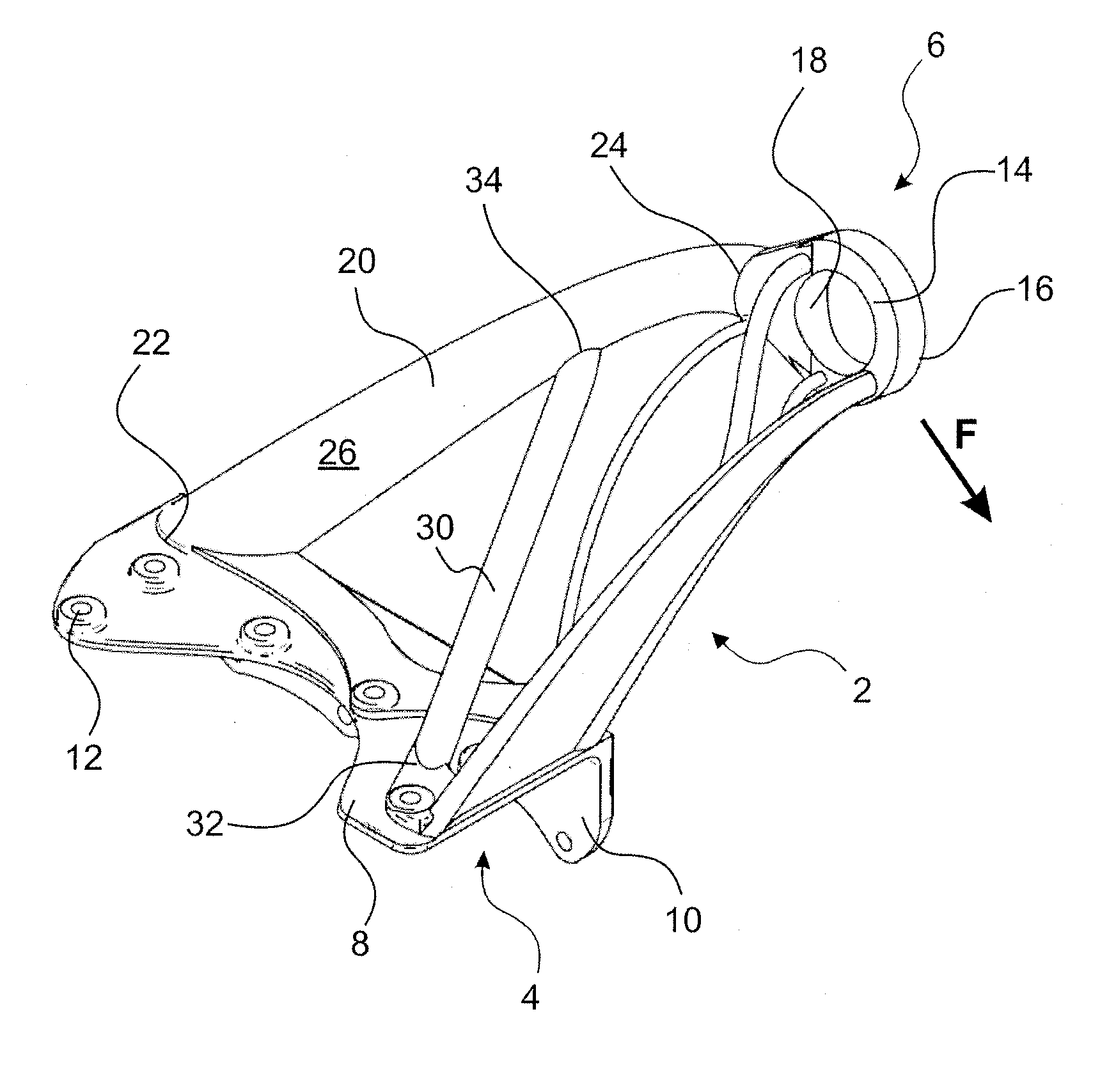
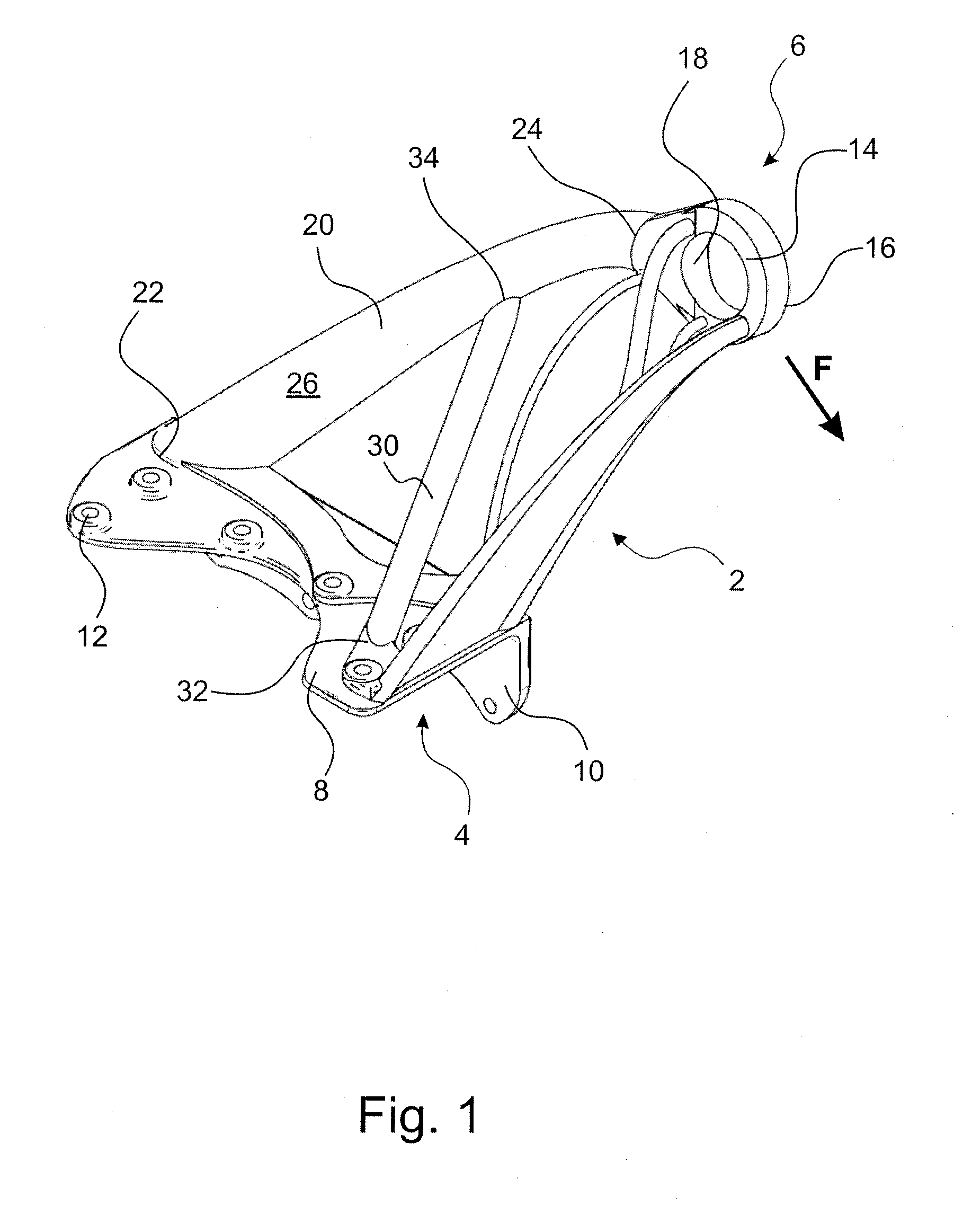
[0029]FIG. 1 shows a structural component 2 which essentially comprises an bracket 4 and an eye 6. The bracket 4 comprises two legs 8, 10 that are arranged perpendicularly to each other, which comprise mounting holes 12. By means of suitable mounting material that is inserted through the mounting holes 12 the bracket 4 is affixed to a crew rest compartment 52 (see FIG. 3).

[0030]The eye 6 comprises two plane parallel plane sides 14, 16. At a right angle to the plane sides 14, 16 the eye 6 comprises a through-hole 18 in which there is a shock-mount element (not shown) which is connected in an articulated manner to a tension-compression rod 19 (see FIG. 3). The eye 6 is arranged in such a manner relative to the bracket 4 that the plane sides 14, 16 extend along a direction F so as to be plane parallel t...


PUM

PropertyMeasurementUnit
angleaaaaaaaaaa
thicknessaaaaaaaaaa
strengthaaaaaaaaaa

Abstract

The invention relates to an elongated supporting pillar for a high-strength structural component, wherein the supporting pillar is designed to absorb bending forces that act transversely to a longitudinal direction of extension of the supporting pillar. The supporting pillar comprises a wall which at least partially encloses an elongated cavity of the supporting pillar. A reinforcement structure is arranged within the cavity and transversely to the direction of longitudinal extension in such a manner that the reinforcement structure can absorb at least some of the bending forces. The reinforcement structure is designed integrally with the wall, wherein both the wall and the reinforcement structure comprise a meltable material.

Description

FIELD OF THE INVENTION[0001]The present invention relates to a supporting pillar for a structural component, for example for an aircraft. In particular, the present invention relates to an elongated supporting pillar for a high-strength structural component, a structural component with a supporting pillar, the use of a structural component in an aircraft, a method for manufacturing a supporting pillar, as well as a computer program element for implementing the method, and a corresponding computer-readable medium.BACKGROUND TO THE INVENTION[0002]In today's commercial aircraft specially constructed structural components are used at highly stressed positions. The attachment device for a crew rest compartment may be an example of such a structural component, wherein the structural component is on the one hand firmly connected to this compartment, while on the other hand the forces introduced into the structural components can be transmitted to the frame elements of the aircraft by way o...

Claims


Application Information

Patent Timeline
Patent Type & Authority Applications(United States)
IPC IPC(8): B64C1/06B21D47/01F16M13/00
CPCB64C7/00Y10T29/49631B64D2011/0076B64D11/00Y10T29/49622B64C1/06
Inventor KLAHN, CHRISTOPHGYSEMBERG, RUDYREHME, OLAF
Owner AIRBUS OPERATIONS GMBH
Learn More