Antenna evaluation apparatus and antenna evaluation method for creating multipath waves around receiving antenna

Active Publication Date: 2011-06-02
PANASONIC INTELLECTUAL PROPERTY CORP OF AMERICA
View PDF3 Cites 5 Cited by
  • Summary
  • Abstract
  • Description
  • Claims
  • Application Information

AI Technical Summary

Benefits of technology

[0034]According to the antenna evaluation apparatus and the antenna evaluation method of the present invention, when evaluating the performance of receiving antennas of a MIMO wireless communication system, it is possible to create a multipath propagation environment including different fadings and different delays for different substreams transmitted from a MIMO transmitter, under an assumption that the substreams travel different propagation paths.
[0035]Moreover, according to the antenna evaluation apparatus and the antenna evaluation method of the present invention, when evaluating the performance of receiving antennas of a MIMO wireless communication system, it is possible t

Problems solved by technology

As a result, a digital communication environment suffers from increased errors in cod

Method used


Image

  • Antenna evaluation apparatus and antenna evaluation method for creating multipath waves around receiving antenna
  • Antenna evaluation apparatus and antenna evaluation method for creating multipath waves around receiving antenna
  • Antenna evaluation apparatus and antenna evaluation method for creating multipath waves around receiving antenna

Examples


first embodiment

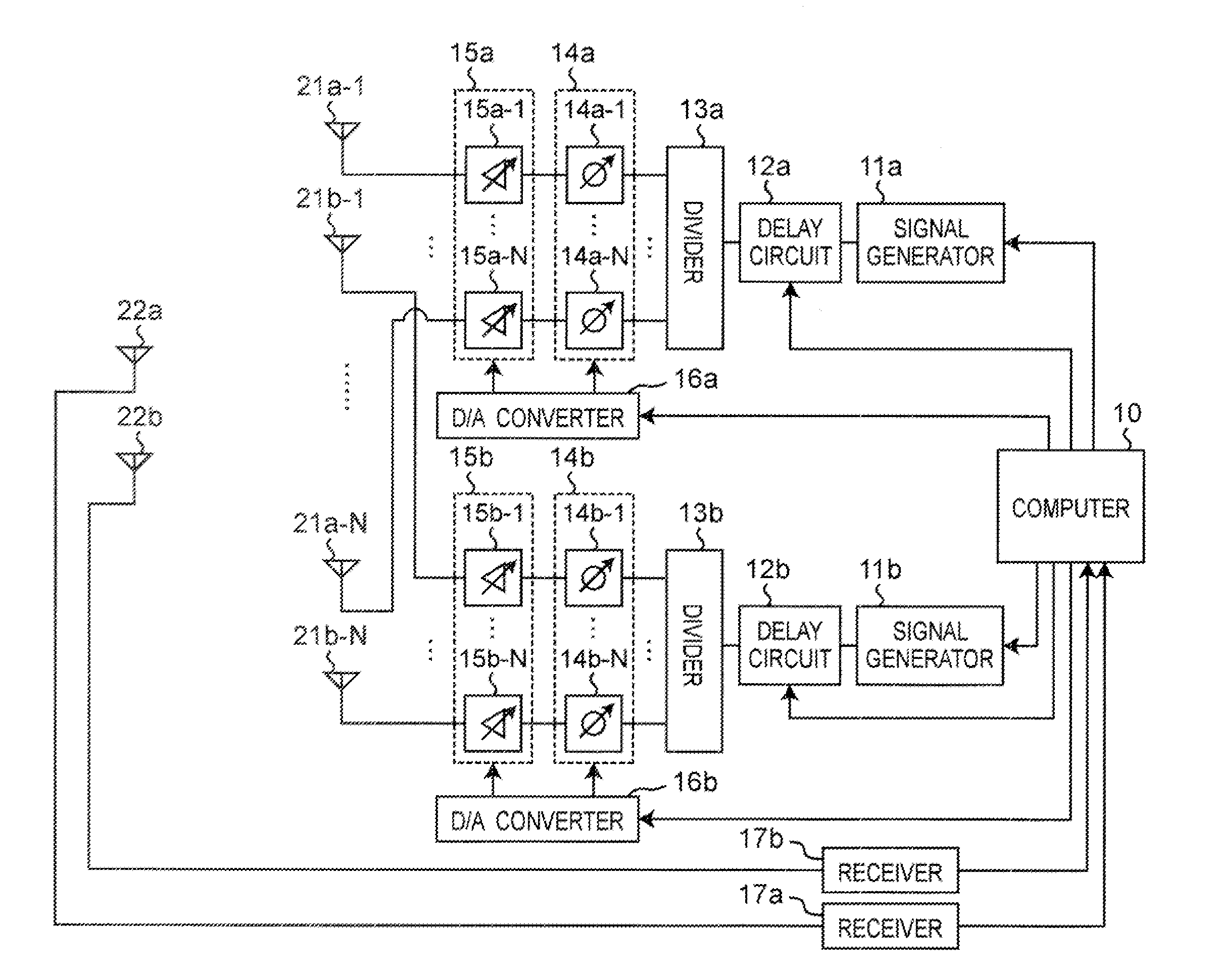
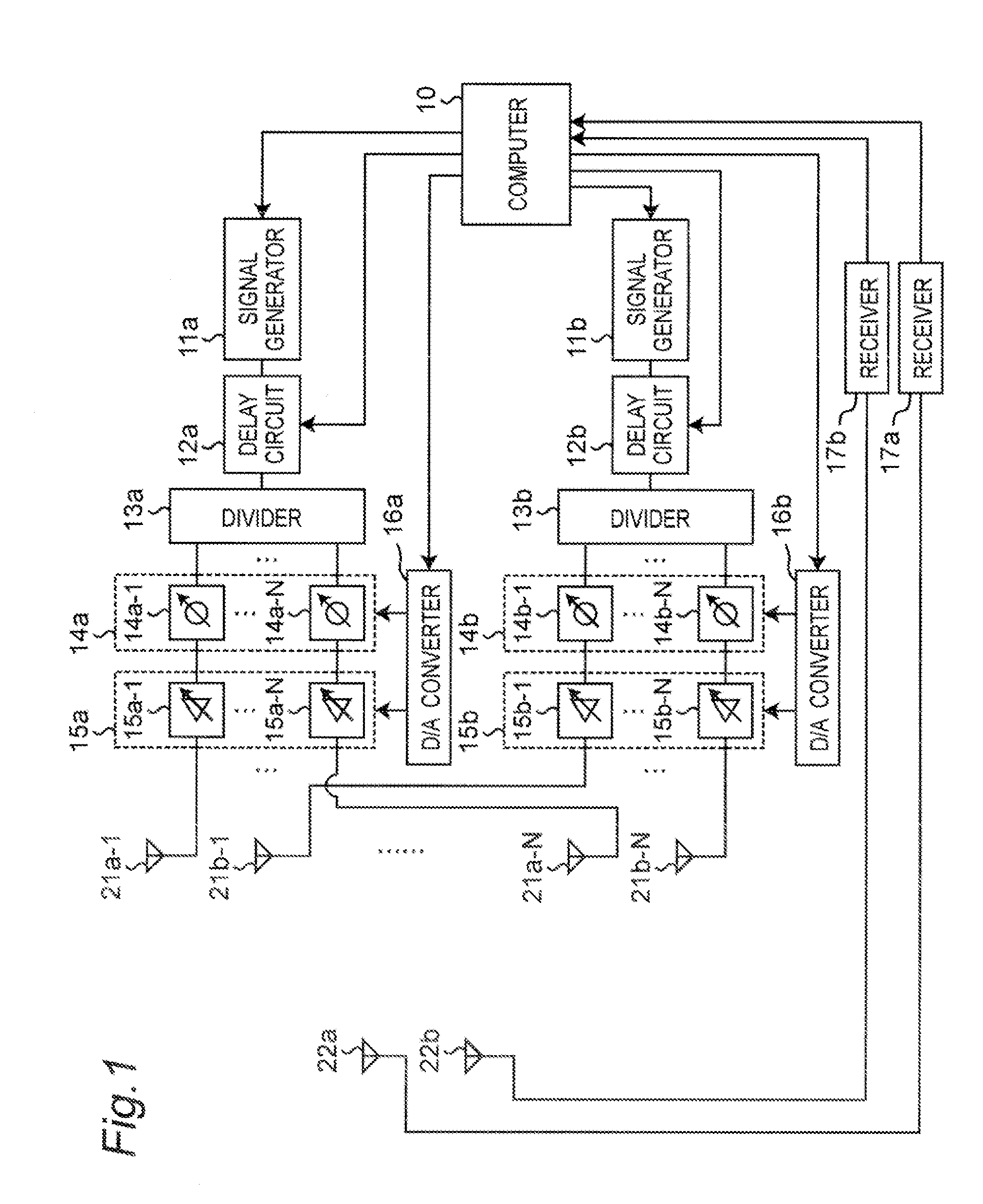
[0077]FIG. 1 is a block diagram showing a configuration of an antenna evaluation apparatus according to a first embodiment of the present invention. The antenna evaluation apparatus includes: two receiving antennas 22a and 22b disposed to be close to each other; and a plurality of scatterer antennas 21a-1 to 21a-N and 21b-1 to 21b-N disposed to surround the receiving antennas 22a and 22b. In the present embodiment, the two receiving antennas 22a and 22b are provided as, for example, two receiving antennas of a MIMO receiver to be evaluated. In addition, the scatterer antennas 21a-1 to 21a-N create multipath waves around the receiving antennas 22a and 22b, the multipath waves corresponding to, for example, a first substream radiated from a first transmitting antenna of a MIMO transmitter having two transmitting antennas and transmitting two substreams. The scatterer antennas 21b-1 to 21b-N create multipath waves around the receiving antennas 22a and 22b, the multipath waves correspon...

second embodiment

[0100]FIG. 9 is a block diagram showing a configuration of an antenna evaluation apparatus according to a second embodiment of the present invention. The present embodiment is characterized by creating a multipath propagation environment where radio waves arrive in groups, each group being in one of a small number of directions and having small angular spread, instead of a multipath propagation environment where incoming waves are uniformly distributed over all angular directions. In this specification, a group of incoming waves occurring in a certain angular direction close together is called a “cluster”. FIG. 10 is a schematic diagram showing clusters of incoming waves in an exemplary MIMO wireless communication system. Radio waves radiated from a MIMO transmitter 200 are reflected by obstacles B1, B2, B3, and B4 such as buildings, and arrive at a MIMO receiver 210 from various directions as clusters C-1, C-2, and C-M. A multipath propagation environment including the clusters cor...

third embodiment

[0122]As described in the “Background Art” section, SCME defines a model including a plurality of delayed waves. In this case, different delayed waves need to produce different fadings, preferably, fadings having no correlation with each other. FIG. 16 is a schematic diagram illustrating the presence of a plurality of delayed waves. FIG. 17 is a graph showing a state in which a first wave and a second wave of FIG. 16 include different fadings. Therefore, an antenna evaluation apparatus of the present embodiment creates a multipath propagation environment including a plurality of delayed waves, and further produces different fadings for different delayed waves.

[0123]FIG. 15 is a block diagram showing a configuration of the antenna evaluation apparatus according to a third embodiment of the present invention. The antenna evaluation apparatus of the present embodiment is characterized by having the same configuration as that of the antenna evaluation apparatus of FIG. 1, and further be...


PUM


Abstract

An antenna evaluation apparatus includes receiving antennas to be evaluated, scatterer antennas provided around them, signal generators, delay circuits, dividers, phase-shift circuits, and attenuation circuits. A computer controls the delay circuits to add delay times to radio frequency signals, and controls the phase-shift circuits and attenuation circuits to change phases and amplitudes of the radio frequency signals to produce a first fading. The antenna evaluation apparatus radiates the radio frequency signals from the scatterer antennas, thus creating multipath waves including delay and fading around the receiving antenna.

Description

TECHNICAL FIELD[0001]The present invention relates to an antenna evaluation apparatus for evaluating the performance of an antenna of a wireless communication apparatus, and relates to an antenna evaluation method using the same antenna evaluation apparatus.BACKGROUND ART[0002]In recent years, wireless terminal apparatuses for mobile communication such as mobile phones have been rapidly developed. When a radio wave arrives at a wireless terminal apparatus from a base station, the radio wave includes multipath waves produced from reflection, scattering, diffraction, or the like due to terrain, structures, and the like in its propagation path, and the radio wave has randomly changing amplitude and phase depending on the location. When receiving a radio wave from the base station as well as moving within its propagation path, fading (i.e., signal level drops, including variation in instantaneous values) occurs due to multipath propagation of the radio wave. As a result, a digital commu...

Claims


Application Information

Patent Timeline
IPC IPC(8): G01R29/10
CPCG01R29/10H01Q3/2682H01Q3/36
Inventor SAKATA, TSUTOMUYAMAMOTO, ATSUSHIAMARI, SATORU
Owner PANASONIC INTELLECTUAL PROPERTY CORP OF AMERICA
Why Eureka
Try Eureka