Low Noise Amplifier

Active Publication Date: 2009-07-02
SYNOPSYS INC
View PDF4 Cites 5 Cited by
  • Summary
  • Abstract
  • Description
  • Claims
  • Application Information

AI Technical Summary

Benefits of technology

[0008]It is also possible to produce a plurality of reference signals and using the plurality of reference signals to switch the one or more resistors into the output path of the amplifier.

Problems solved by technology

One of the known issues with the prior art low noise amplifiers is to ensure that the low noise amplifiers have sufficient headroom at the output to ensure that an amplified input signal is not saturated at the output.

Method used


Image

  • Low Noise Amplifier
  • Low Noise Amplifier

Examples


Embodiment Construction

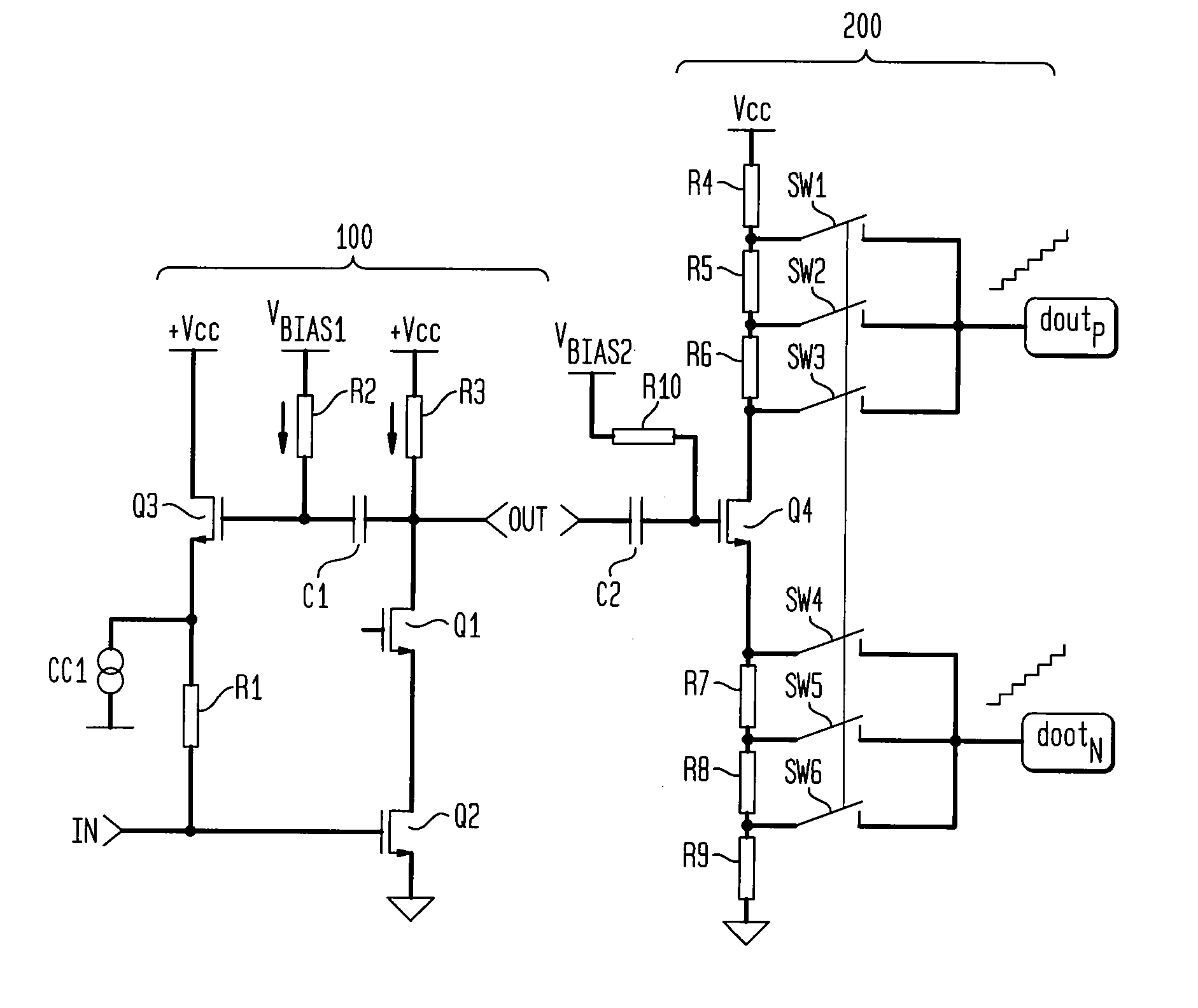
[0011]FIG. 1 illustrates an example of a low noise amplifier 100 and a conversion stage 200 according to an aspect of the invention. The low noise amplifier 100 of FIG. 1 is an example of a common-source amplifier in which the input signal IN is applied to the gate of a second transistor Q2 to control the signal-drain current. The output signal OUT is sensed across a third resistor R3 which is connected between a supply voltage Vcc and the drain of the transistor Q2. The third resistor R3 can be replaced by a bank of resistors which can be selected and act as a coarse gain for the low noise amplifier 10. Typically the selection of the resistors allows the course gain to be selected in steps of 6 dB, but this is not limiting of the invention. A first transistor Q1 is placed between the third resistor R3 and the drain of the second transistor Q2. The first transistor Q1 is a cascade transistor as known in the art and is used to isolate parasitic capacitance associated with the second ...


PUM


Abstract

The invention teaches an amplifier (100) with an input signal (IN) coupled to the gate of a second transistor (Q2) and an output signal (OUT) coupled to an output node between a third resistor (R3) and the drain of the second transistor (Q2). A third transistor (Q3) is coupled in parallel between the output node and the gate of a second transistor (Q2). A first bias signal (Vbias) is coupled to the output node and the gate of the third transistor (Q3). The amplifier preferably also includes a plurality of switchable resistors coupled to the output node to adjust the output for process variations.
The invention also describes a method of compensating for process variations in an output of an amplifier which comprises producing a reference signal dependent on the difference between a reference value and an actual value and switching one or more resistors into the output of the amplifier to adjust the output of the amplifier to reflect the process variations. The reference signal is produced by comparing the differential inputs of a reference input produced from a reference potential across a first resistor 302 having a reference value in series with a constant current source 304 and an actual input produced from an actual potential across a second resistor 303 having substantially the same reference value. The second resistor 303 is in series with the channel of a transistor 301.

Description

TECHNICAL FIELD OF THE INVENTION [0001]The invention relates to an amplifier (LNA) such as a low noise amplifier.BACKGROUND OF THE INVENTION [0002]A low noise amplifier (LNA) is a type of electronic amplifier used in communication systems to amplify very weak signals captured by an antenna.[0003]One of the known issues with the prior art low noise amplifiers is to ensure that the low noise amplifiers have sufficient headroom at the output to ensure that an amplified input signal is not saturated at the output. In the prior art this can be achieved by providing a bank of selectable resistors between an output node and a voltage supply. One or more resistors can be selected in order to ensure that an output signal at the output node is not saturated.SUMMARY OF THE INVENTION [0004]The invention discloses an amplifier with an input coupled to the gate of a second transistor and an output coupled to an output node between a third resistor and the drain of the second transistor. A third t...

Claims


Application Information

Patent Timeline
Patent Type & Authority Applications(United States)
IPC IPC(8): H03F1/22
CPCH03F1/223H03F1/26H03F3/195H03F2200/451H03F2200/21H03F2200/294H03F2200/421H03F2200/18
Inventor REIS, RICARDO DOS SANTOS
Owner SYNOPSYS INC
Why Eureka
Try Eureka