Percussive mechanism with an electrodynamic linear drive

a percussive mechanism and electrodynamic technology, applied in the direction of percussive tools, manufacturing tools, portable drilling machines, etc., can solve the problems of significant vibration noise, helical springs have the disadvantage of breaking, and the effect of affecting the efficiency of the percussion system

Inactive Publication Date: 2013-09-17
WACKER NEUSON SE
View PDF29 Cites 6 Cited by
  • Summary
  • Abstract
  • Description
  • Claims
  • Application Information

AI Technical Summary

Benefits of technology

[0012]The underlying object of the present invention is to indicate a percussion mechanism having an electrodynamic linear drive in which an electromagnetic drive force that is used to reverse the direction of movement of a linearly moved drive unit is supported without having to accept the disadvantages associated with other types of percussion mechanisms.
[0013]According to the present invention, this object is achieved by a percussion. A percussion mechanism according to the present invention has an electrodynamic linear drive, a drive element that can be moved back and forth in a percussion mechanism housing by the linear drive, a percussion element that strikes a tool, and a coupling, or a coupling device, that is effective between the drive element and the percussion element, via which the movement of the drive element is capable of being transmitted to the percussion element. According to the present invention, the percussion mechanism is characterized in that, seen in the direction of impact, a reversing hollow space is effectively provided before and / or after the drive element, and in that the reversing hollow space is capable of being separated at least at times from the surrounding environment, in such a way that in the reversing hollow space is capable of being separated at least at times from the surrounding environment, in such a way that in the reversing hollow space it is possible to produce a reversing air spring that acts against the drive element and / or against the percussion element.

Problems solved by technology

However, in the coils of the stator that surrounds the runner, heat loss occurs that has an adverse effect on the efficiency of the percussion system.
In addition, helical springs have the disadvantage that they can break due to the high impact speeds.
Also, significant vibration noise results.
Moreover, if the helical spring is too weak, given a correspondingly high impact speed of the percussion piston the spring can bottom out, which can result in damage to the percussion mechanism.

Method used


Image

  • Percussive mechanism with an electrodynamic linear drive
  • Percussive mechanism with an electrodynamic linear drive
  • Percussive mechanism with an electrodynamic linear drive

Examples


Embodiment Construction

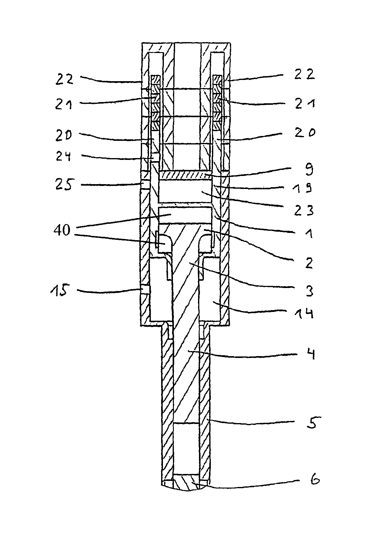
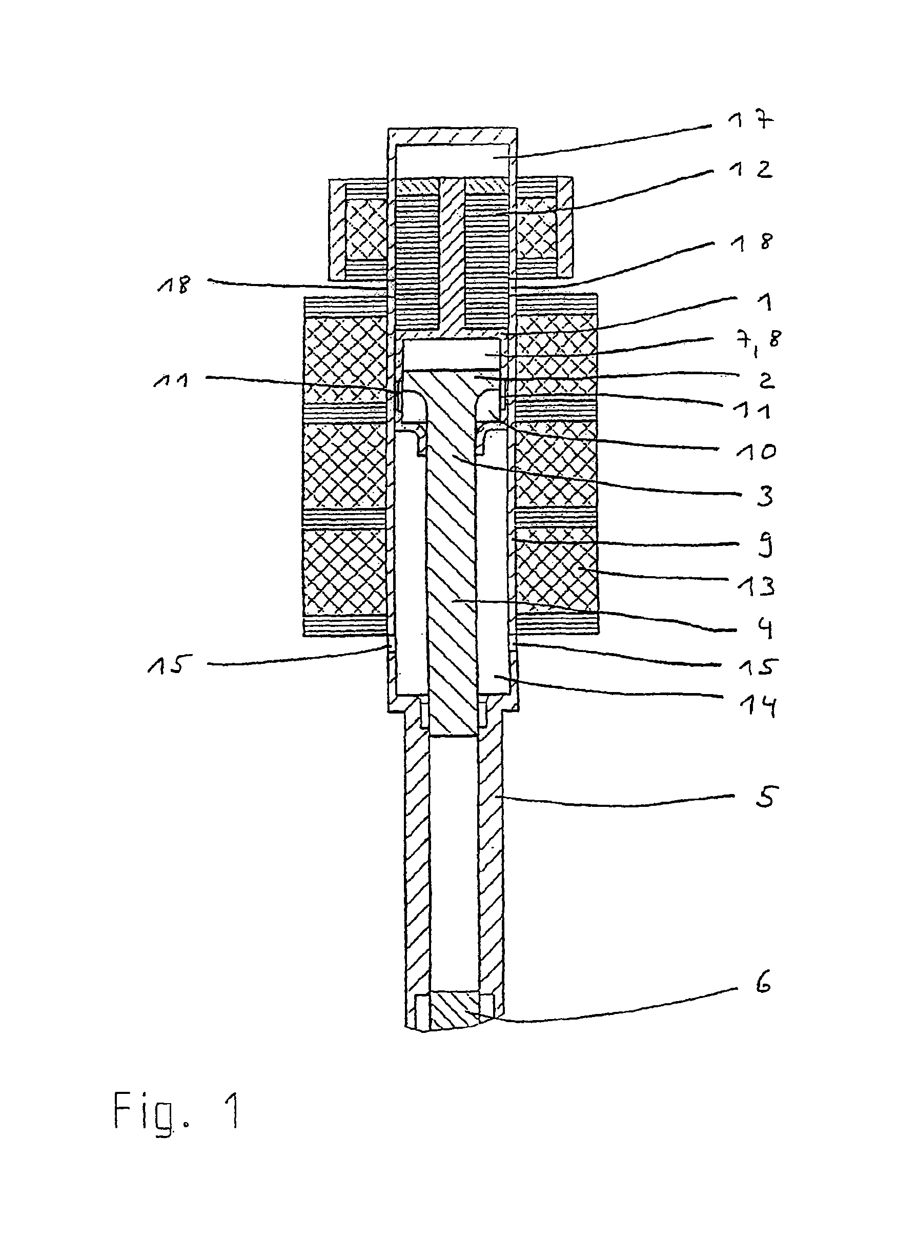
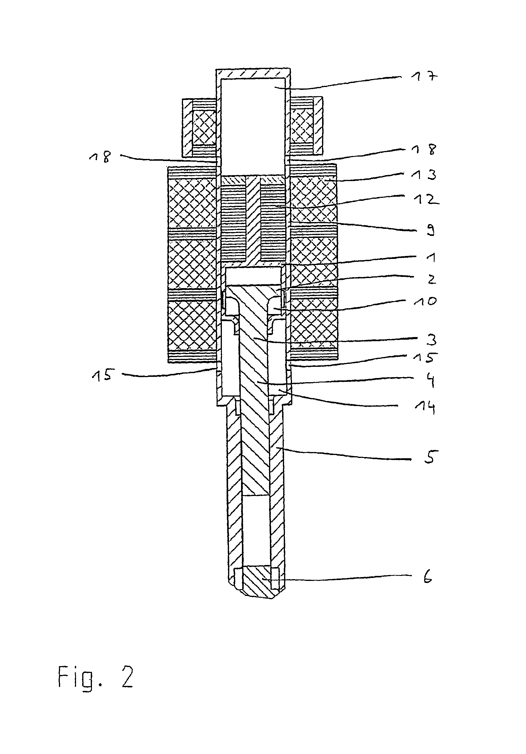
[0048]FIGS. 1 to 3 and 4 to 6 show two different specific embodiments of the percussion mechanism according to the present invention, realized as a pneumatic spring percussion mechanism, in a highly simplified schematic representation. In particular, known components such as electrical terminals and sensors are omitted because they do not relate to the present invention. The percussion mechanism according to the present invention can be used particularly advantageously in a drilling and / or striking hammer. Here, various types of percussion mechanism can be realized, of which in particular pneumatic spring percussion mechanisms are particularly suitable.

[0049]FIGS. 1 to 3 show a first specific embodiment of the present invention having a pneumatic spring percussion mechanism driven by an electrodynamic linear drive. Here, a drive unit (explained in more detail below) is shown in the representation in FIG. 1 in an extreme upper / rear position; in FIG. 2 is shown in a center position an...


PUM

PropertyMeasurementUnit
movementaaaaaaaaaa
elasticaaaaaaaaaa
areaaaaaaaaaaa

Abstract

A percussive mechanism, which is provided in the form of an, e.g. pneumatic spring percussive mechanism, comprises an electrodynamic linear drive, a drive piston, which can be reciprocally moved inside a percussive mechanism housing by the linear drive, and a percussive piston. An additional hollow space is provided in front of and / or behind the drive piston and can be isolated at least in part from the surrounding area so that a pneumatic spring can be created in the additional hollow space. The pneumatic spring slows the drive piston at its returning points and facilitates a returning motion without loading the electrodynamic linear drive.

Description

BACKGROUND OF THE INVENTION[0001]1. Field of the Invention[0002]The present invention relates to a percussion mechanism having an electrodynamic linear drive.[0003]2. Description of the Related Art[0004]Drilling and / or striking hammers (designated “hammers” hereinafter) are standardly driven by electric motors in which a rotor rotates a drive shaft. The rotational movement is converted into an oscillating linear movement that is communicated to a drive element in a percussion mechanism. Here, as a percussion mechanism in particular a pneumatic spring mechanism is suitable in which a drive piston that acts as a drive element is moved back and forth.[0005]From DE 102 04 861 A1, a pneumatic spring percussion mechanism is known for a hammer in which a drive piston is capable of being driven by an electrodynamic linear drive. The drive piston is coupled to a runner of the linear drive, so that the linear back-and-forth movement of the runner is transmitted to the drive piston. The moveme...

Claims


Application Information

Patent Timeline
Patent Type & Authority Patents(United States)
IPC IPC(8): B23B45/16B25D13/00B25D11/00B25D16/00B25D9/00
CPCB25D11/064B25D2250/375
Inventor BERGER, RUDOLFSTENZEL, OTTO W.SCHMID, WOLFGANG
Owner WACKER NEUSON SE
Why Eureka
Try Eureka