Electrical Devices Including Dendritic Metal Electrodes

Active Publication Date: 2011-10-20
ARIZONA STATE UNIVERSITY
View PDF105 Cites 44 Cited by
  • Summary
  • Abstract
  • Description
  • Claims
  • Application Information

AI Technical Summary

Problems solved by technology

However, electrode designs commonly used with electrically active structures suffer from a number of disadvantages.
The dimensions of these electrodes (e.g., their line widths and the spaces between them) are generally large due to manufacturing cost limitations.
The relatively large space between electrodes can create a high series resistance between the current generating sites and the top electrode, leading to inefficient energy collection from the areas of the current generating structure that are farthest from the electrodes.
Packing

Method used


Image

  • Electrical Devices Including Dendritic Metal Electrodes
  • Electrical Devices Including Dendritic Metal Electrodes
  • Electrical Devices Including Dendritic Metal Electrodes

Examples


Embodiment Construction

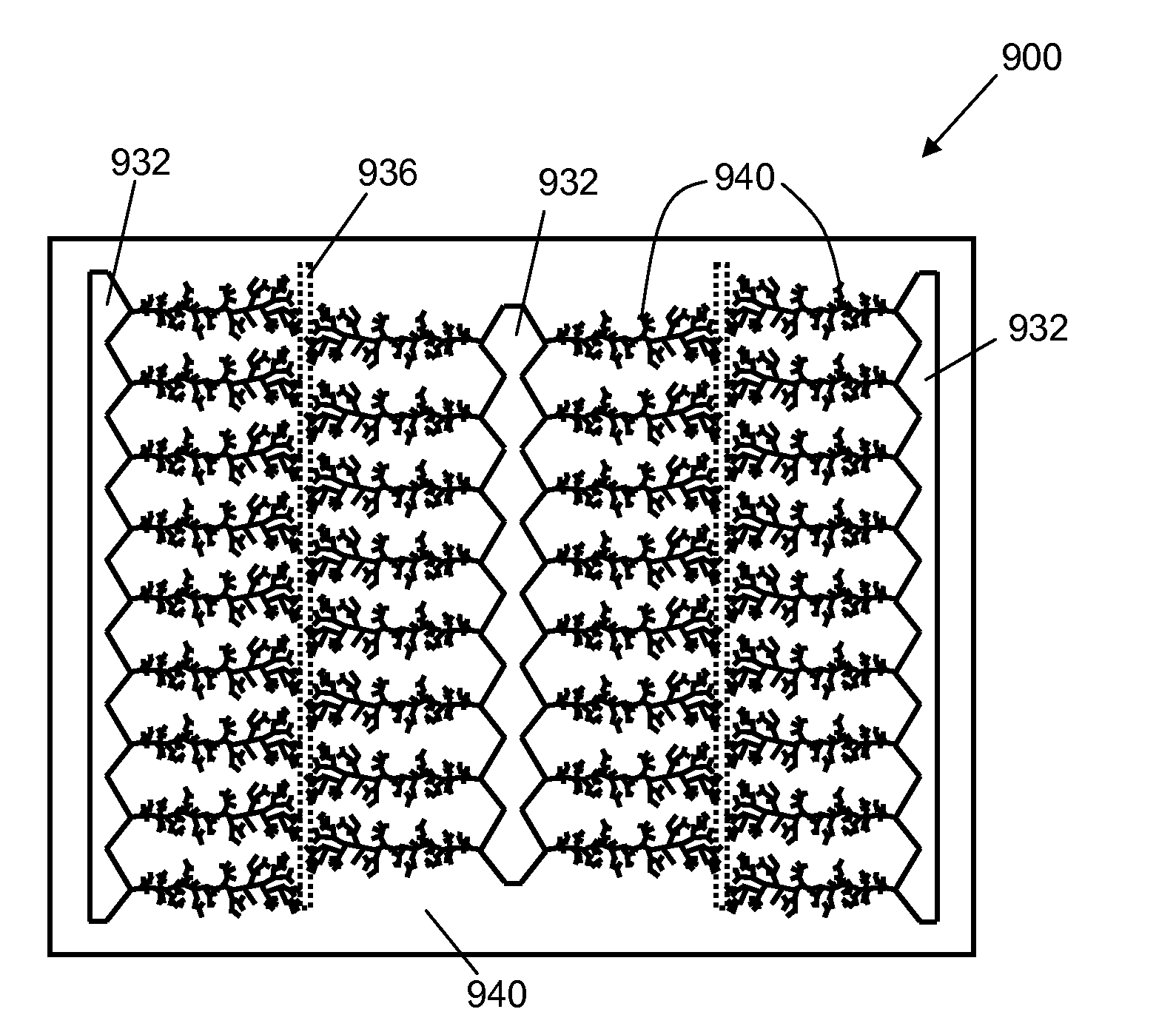
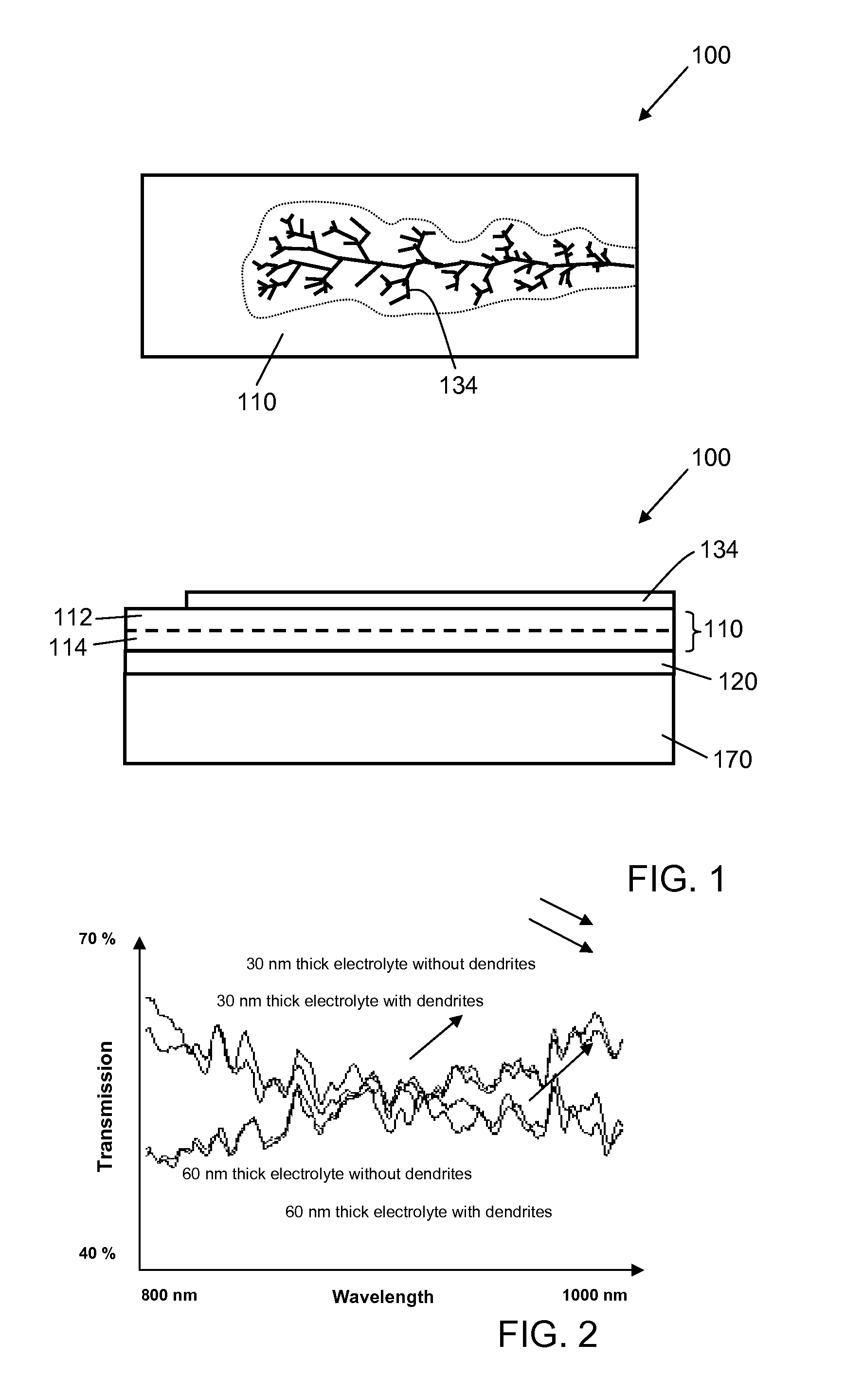
[0044]One example of an electrical device according to one embodiment of the invention is shown in schematic top view and schematic cross-sectional view in FIG. 1. Electrical device 100 includes an electrically active structure 110, in this example a current generating structure including an n-type semiconductor layer 112 and a p-type semiconductor layer 114. On one side of the electrically active structure 110 is a first electrode that includes at least one dendritic metal structure 134. On the other side of the electrically active structure 110 is a second electrode 120 (disposed on substrate 170). In this example, in which the electrically active structure is a current generating structure, the at least one dendritic metal structure and the second electrode are in electrical contact with the current generating structure. In use, generated current (e.g., photogenerated current) runs between the at least one dendritic metal electrode and the second electrode (i.e., in either direct...


PUM


Abstract

The present invention relates generally to electrical devices. The present invention relates more particularly to electrical devices including dendritic metal electrodes. One aspect of the present invention is an electrical device comprising a first electrode comprising at least one dendritic metal structure; a second electrode; and an electrically active structure disposed between the dendritic metal structure and the second electrode.

Description

CROSS REFERENCE TO RELATED APPLICATIONS[0001]The present application claims priority to U.S. Provisional Patent Application Ser. No. 61 / 120,747, filed Dec. 8, 2008, which is hereby incorporated by reference in its entirety.BACKGROUND OF THE INVENTION[0002]1. Field of the Invention[0003]The present invention relates generally to electrical devices. The present invention relates more particularly to electrical devices including dendritic metal electrodes.[0004]2. Technical Background[0005]Electrically active structures find use in a variety of applications. One type of electrically active structure is a current generating structure, in which current is generated in response to an external stimulus. For example, solar cells are based on structures that generate current in response to absorption of solar radiation. This current can be collected to provide electrical energy. Similarly, optical sensors such as photodetectors can be based on current generating structures; absorption of an ...

Claims


Application Information

Patent Timeline
IPC IPC(8): H01L31/102H01L23/48H01L21/326
CPCC25D7/08G02F1/1343G02F2201/124G06F3/044H01L31/022408H01L31/022425Y02E10/50H01L31/0224G06F3/0445
Inventor KOZICKI, MICHAEL
Owner ARIZONA STATE UNIVERSITY
Why Eureka
Try Eureka