Voltage operation system

Active Publication Date: 2011-10-20
REALTEK SEMICON CORP
View PDF4 Cites 3 Cited by
  • Summary
  • Abstract
  • Description
  • Claims
  • Application Information

AI Technical Summary

Benefits of technology

[0010]Therefore, the present invention can avoid that the working voltage is too low outputting pulse signal and making the false action. Furthermore, th

Problems solved by technology

The voltage level may be too low to make the power on reset circuit, which cannot work in the normal status.
However, at the transient time of system turning on or turning off, the instantaneous current

Method used


Image

  • Voltage operation system
  • Voltage operation system
  • Voltage operation system

Examples


Embodiment Construction

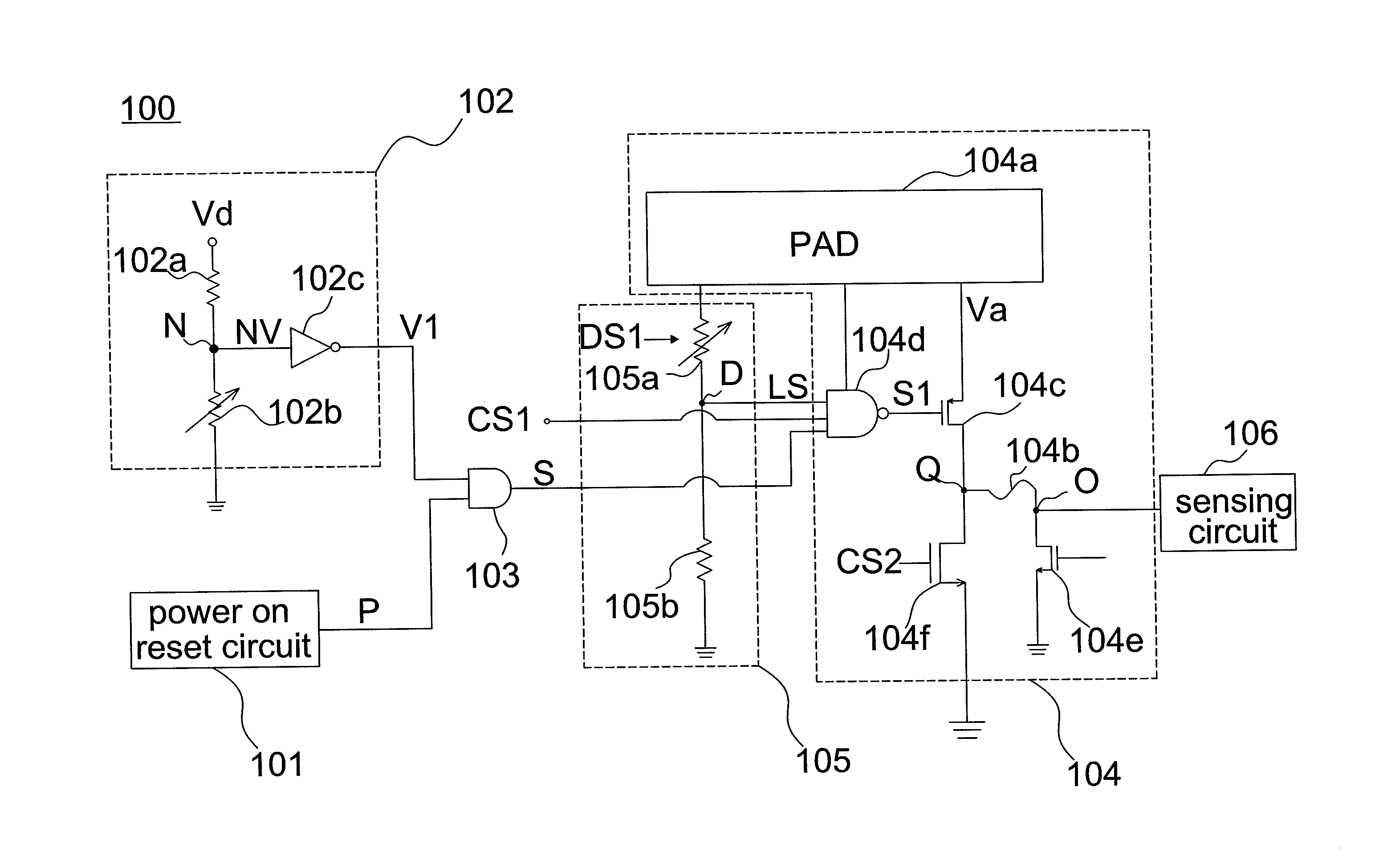
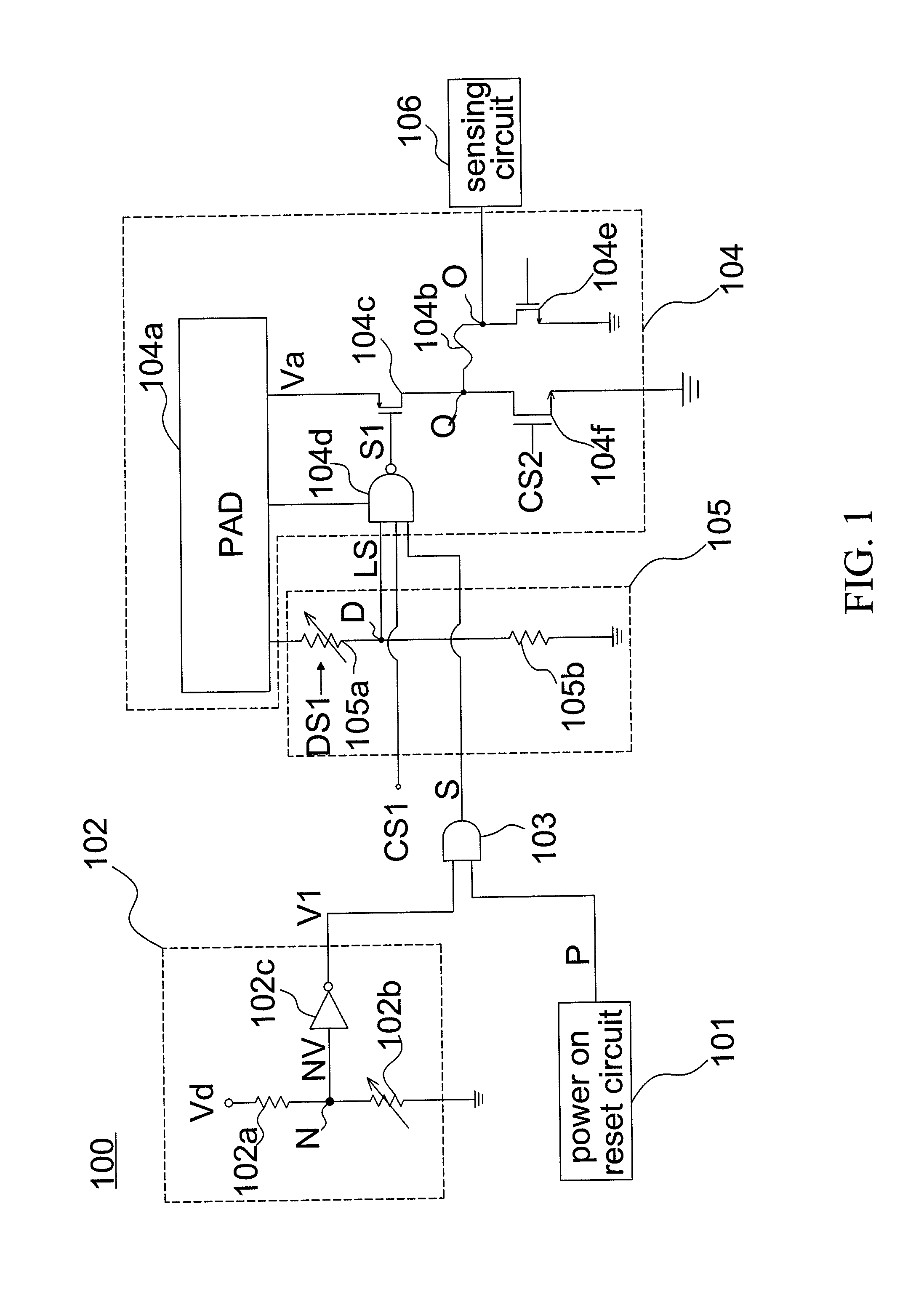
[0018]Please refer to FIG. 1 which shows a schematic diagram illustrating a voltage operating system according to one embodiment of the invention. As shown in FIG. 1, the voltage operating system 100 comprises a power on reset circuit 101, a voltage detecting circuit 102 and an operating signal generating circuit 103.

[0019]The power on reset circuit 101 generates a power on reset signal P to the operating signal generating circuit 103; the voltage detecting circuit 102 detect voltage level of a working voltage Vd to output a voltage detecting signal V1, so that voltage level of voltage detecting signal V1 will change with the working voltage Vd; the operating signal generating circuit 103 couples to voltage detecting circuit 102 and operating signal generating circuit 103. Wherein, operating signal generating circuit 103 receives power on reset signal P and voltage detecting signal V1 to output an operating signal S by power on reset signal P and voltage detecting signal V1.

[0020]In...


PUM


Abstract

A voltage operation system is disclosed. The voltage operation system includes: a power on rest circuit, a voltage detecting circuit, an operating signal generating circuit, and an electronic fuse circuit. The power on rest circuit is used for generating a power on rest signal. The voltage detecting circuit detects an operating voltage to output a voltage detecting signal. The operating signal generating circuit, coupled to the power on rest circuit and the voltage detecting circuit, for outputting a operating signal. The electronic fuse circuit fuses or not according to a lock signal, a fuse signal, and the operating signal.

Description

[0001]This application claims the benefit of the filing date of Taiwan Application Ser. No. 099111978, filed on Apr. 16, 2010, the content of which is incorporated herein by reference.BACKGROUND OF THE INVENTION[0002](a) Field of the Invention[0003]The present invention relates to a voltage operating system. More specifically, this invention relates to a voltage operating system can detect status of voltage to prevent false action.[0004](b) Description of the Related Art[0005]A power on reset circuit is usually an analog circuit, so that voltage level has unknown status easily. The voltage level may be too low to make the power on reset circuit, which cannot work in the normal status. Generally, the melting status of a fuse can be decided at initial setting of the electronic fuse system. In other words, a user can decide whether melts down the fuse to change the electronic fuse system voltage level and output different outputs at initial setting.[0006]However, at the transient time ...

Claims


Application Information

Patent Timeline
IPC IPC(8): H03L7/00
CPCH03K17/22
Inventor LIU, KAI-YIN
Owner REALTEK SEMICON CORP
Why Eureka
Try Eureka