Motor control device and vehicle brake hydraulic pressure control apparatus

a technology of hydraulic pressure control and control device, which is applied in the direction of dynamo-electric converter control, motor/generator/converter stopper, fluid coupling, etc., can solve the problems of shortening the length of one cycle, increasing the operation noise, and generating vibration in the motor, so as to facilitate detection, enhance the marketability of the vehicle hydraulic brake fluid control apparatus, and reduce the operation noise of the motor and the pump driven by the motor.

Active Publication Date: 2014-03-06
AUTOLIV NISSIN BRAKE SYST JAPAN CO LTD
View PDF7 Cites 3 Cited by
  • Summary
  • Abstract
  • Description
  • Claims
  • Application Information

AI Technical Summary

Benefits of technology

[0009]The invention provides a motor control device and a vehicle brake hydraulic pressure control apparatus that make it possible to easily detect a voltage between terminals of a motor irrespective of a driving frequency of the motor.
[0011]With this configuration, the off control is performed for the motor with the second period, which is longer than the first period, separately from the on / off control performed by the driving controller. Therefore, it is possible to easily detect the voltage between the terminals during a time period in which the motor is off, irrespective of the driving frequency of the motor. As a result, even if the driving frequency of the motor is increased, it is possible to reduce operating noise of the motor.
[0014]With this configuration, it is possible to control the number of rotations of the motor and / or to detect malfunction of the motor.
[0018]With this configuration, even if a driving frequency of the motor in the vehicle hydraulic brake fluid control apparatus is increased, operation noise of the motor and operation noise of a pump driven by the motor can be reduced. As a result, the marketability of the vehicle hydraulic brake fluid control apparatus can be enhanced.
[0019]With the above configurations, it is facilitated to detect the voltage between the terminals during the time period in which the motor is off, irrespectively of the driving frequency of the motor. Therefore, even if the driving frequency of the motor is increased, the operation noise of the motor and the operation noise of the pump drive by the motor can be reduced.

Problems solved by technology

Incidentally, when a motor is PWM controlled, turning on / off of a motor current makes fluctuation of the rotation of the motor be more large as the cycle of the PWM control becomes longer, which results in generation of vibrations in the motor and an increase of the operation noise thereof.
However, if the driving frequency is increased, a length of one cycle becomes short.
This makes it difficult to detect a voltage between terminals of the motor.

Method used


Image

  • Motor control device and vehicle brake hydraulic pressure control apparatus
  • Motor control device and vehicle brake hydraulic pressure control apparatus
  • Motor control device and vehicle brake hydraulic pressure control apparatus

Examples


Embodiment Construction

[0027]Embodiments of the invention will be described in detail with reference to the accompanying drawings.

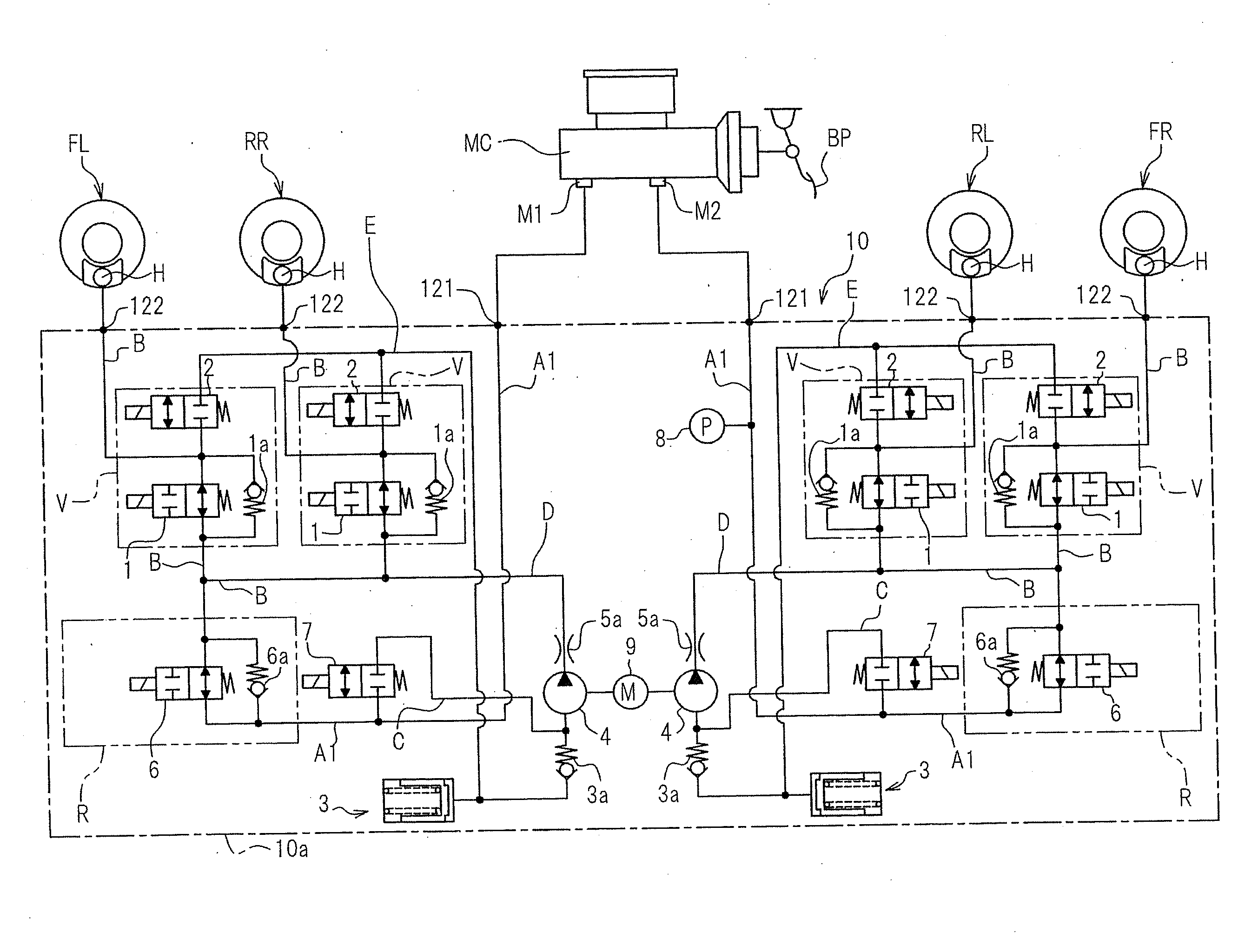
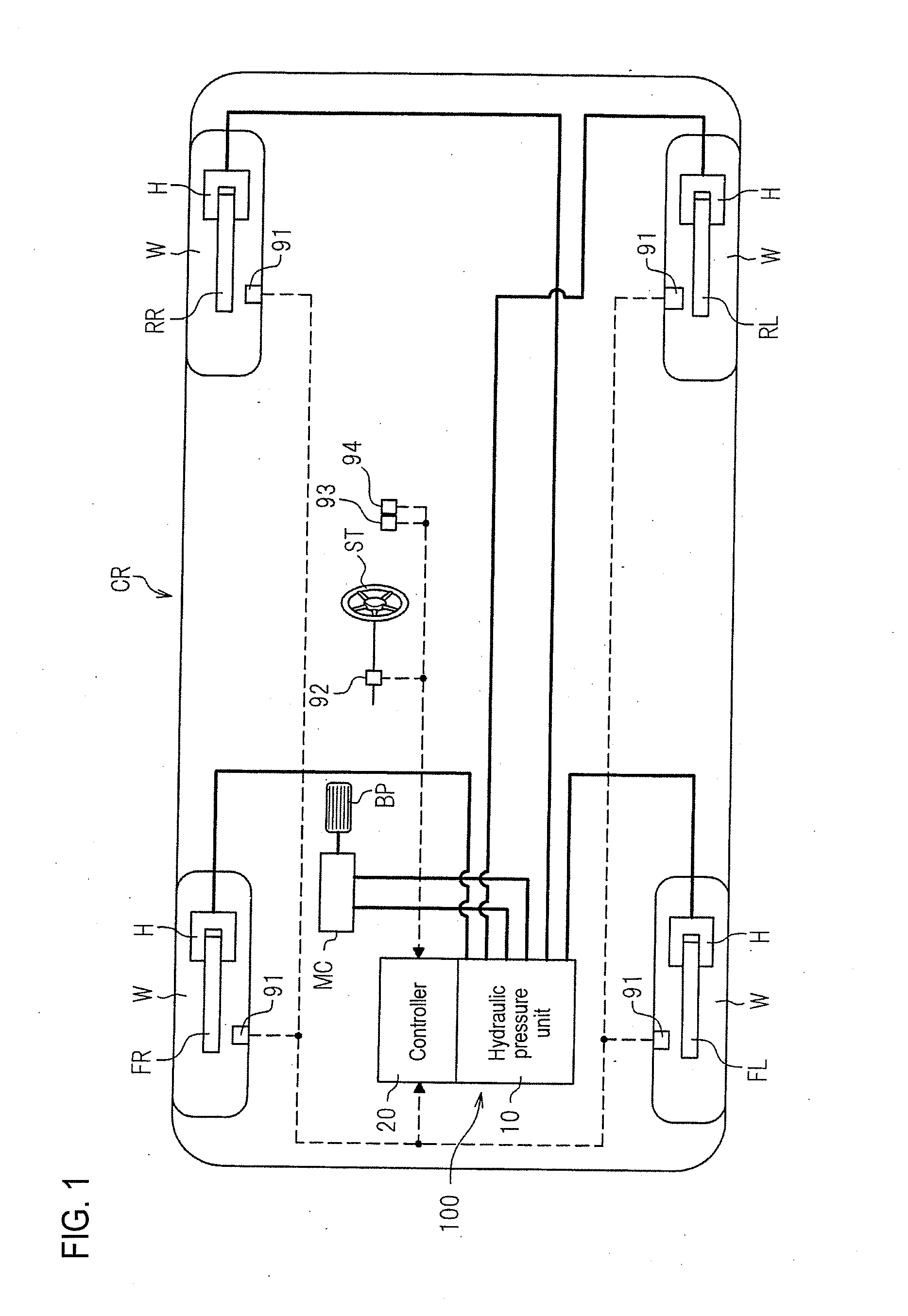
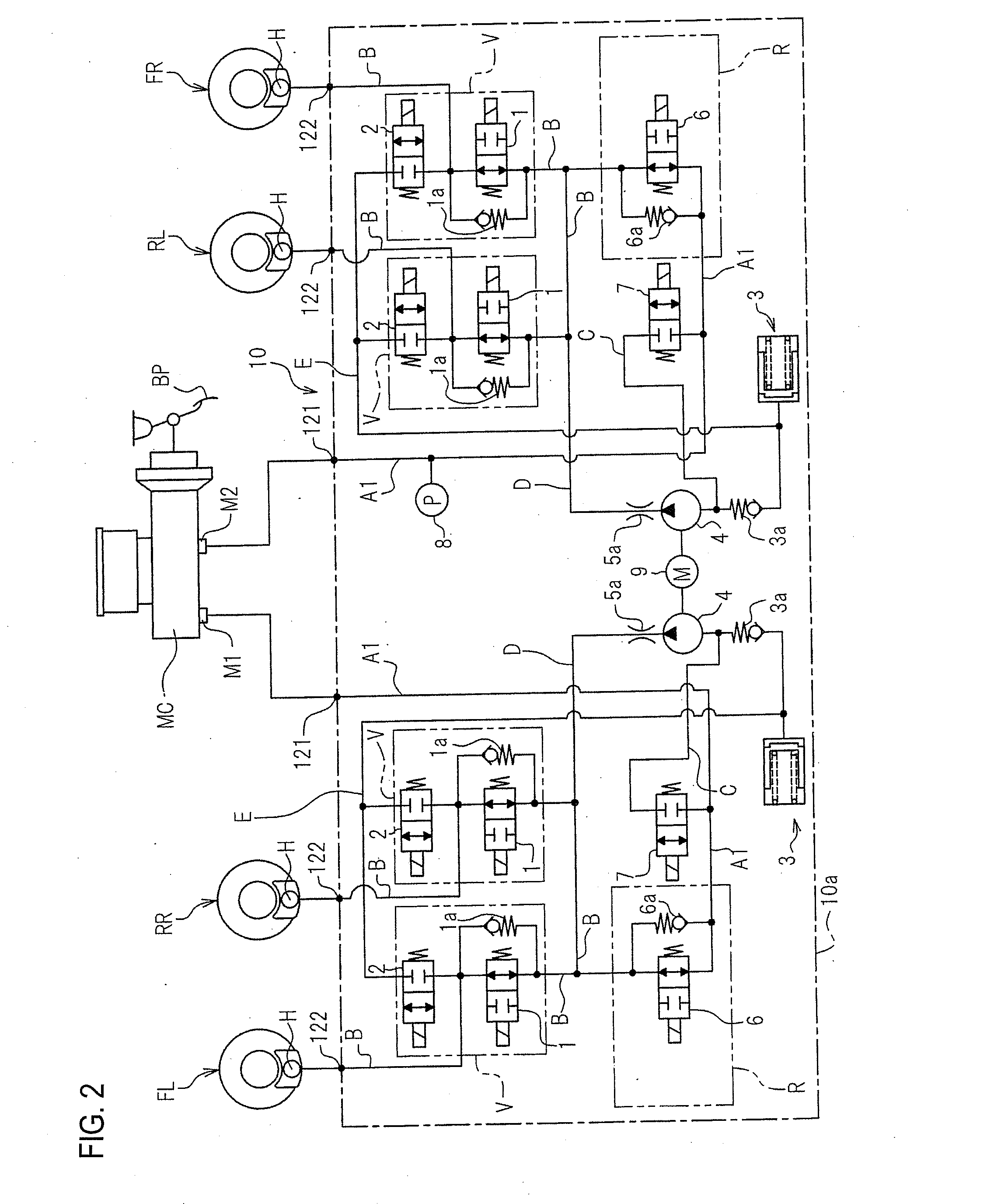
[0028]FIG. 1 shows a vehicle behavior control apparatus 100 as an example of a vehicle brake hydraulic pressure control apparatus. The vehicle behavior control apparatus 100 controls a braking force (a brake fluid pressure) imparted to respective wheels W of a vehicle CR. The vehicle behavior control apparatus 100 mainly includes a hydraulic pressure unit 10 in which fluid lines (hydraulic pressure lines) and various parts are provided and a controller 20 that controls the various parts in the hydraulic pressure unit 10 as required.

[0029]Wheel speed sensors 91, a steering angle sensor 92, a lateral acceleration sensor 93, and a yaw rate sensor 94 are connected to the controller 20. The wheel speed sensors 91 detect wheel speeds of the wheels W. The steering angle sensor 92 detects a steering angle of a steering wheel ST. The lateral acceleration sensor 93 detects an acceleratio...


PUM


Abstract

A motor control device (a motor driver) for controlling, by a duty control, a current supplied to a motor includes a driving controller, an off controller, and a voltage acquiring section (an A / D conversion processor, a sampling section). The driving controller performs on / off control of the current supplied to the motor with a first period. The off controller performs off control for the motor with a second period separately from the on / off control performed by the driving controller. The second period is longer than the first period. The voltage acquiring section acquires a voltage between terminals of the motor during a time period in which the off control is performed by the off controller.

Description

CROSS REFERENCE TO RELATED APPLICATION[0001]This application is based on and claims priority under 35 U.S.C. §119 to Japanese Patent Application No. 2012-194656 (filed on Sep. 5, 2012), the entire contents of which are incorporated herein by reference.BACKGROUND [0002]1. Technical Field[0003]The invention relates to a motor control device that controls a motor by monitoring a voltage between terminals of a motor and a vehicle brake hydraulic pressure control apparatus including the motor control device.[0004]2. Related Art[0005]In motor control devices, a rotation state of a motor is detected in order to control the number of motor revolutions and / or detect an abnormality in the motor. The rotation state of the motor can be determined based on a counter electromotive force of the motor which is obtained by detecting a voltage between terminals of the motor.[0006]To obtain the counter electromotive force accurately, it is desirable to detect the voltage between the terminals at insta...

Claims


Application Information

Patent Timeline
Patent Type & Authority Applications(United States)
IPC IPC(8): B60T13/74H02P7/29B60T8/34B60T17/22H02P7/291
CPCH02P7/29B60T13/745
Inventor NOMURA, NOBUYUKI
Owner AUTOLIV NISSIN BRAKE SYST JAPAN CO LTD
Why Eureka
Try Eureka