Distributed Optical Fibre Sensor

a technology of optical fibre and diffusion optical fiber, applied in the direction of converting sensor output, measurement devices, instruments, etc., can solve the problems high attenuation, and difficult manufacturing of high birefringence fibres, so as to reduce signal fading

Inactive Publication Date: 2011-10-20
FOTECH SOLUTIONS
View PDF6 Cites 40 Cited by
  • Summary
  • Abstract
  • Description
  • Claims
  • Application Information

AI Technical Summary

Benefits of technology

[0012]The invention provides a distributed optical fibre sensor which uses a sensor fibre preferably having a low or zero intrinsic birefringence and whose polarisation properties are responsive to an environmental influence such as pressure. Probe light pulses having a diversity of launch polarisati

Problems solved by technology

The above technique can be hard to use because of additional, unwanted, random levels of intrinsic and environmentally-induced birefringence in the optical fibre.
High birefringence fibres are relatively expens

Method used


Image

  • Distributed Optical Fibre Sensor
  • Distributed Optical Fibre Sensor
  • Distributed Optical Fibre Sensor

Examples


Embodiment Construction

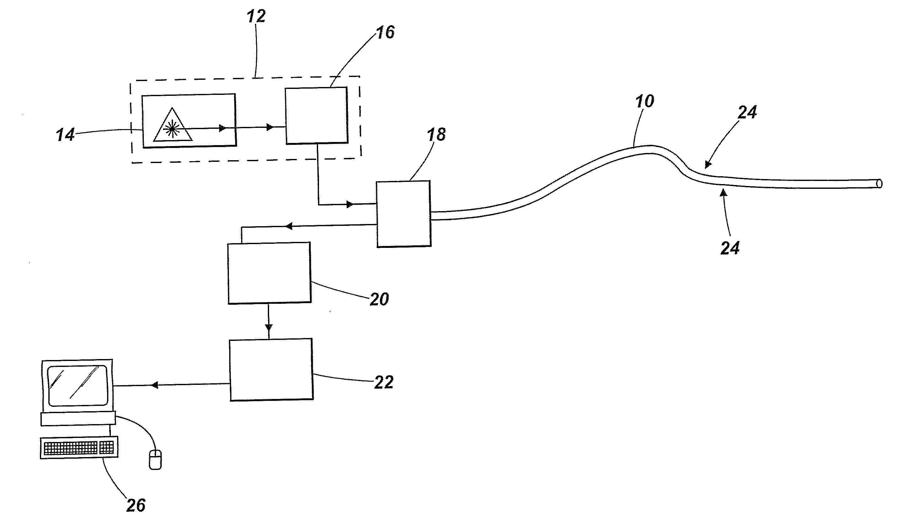
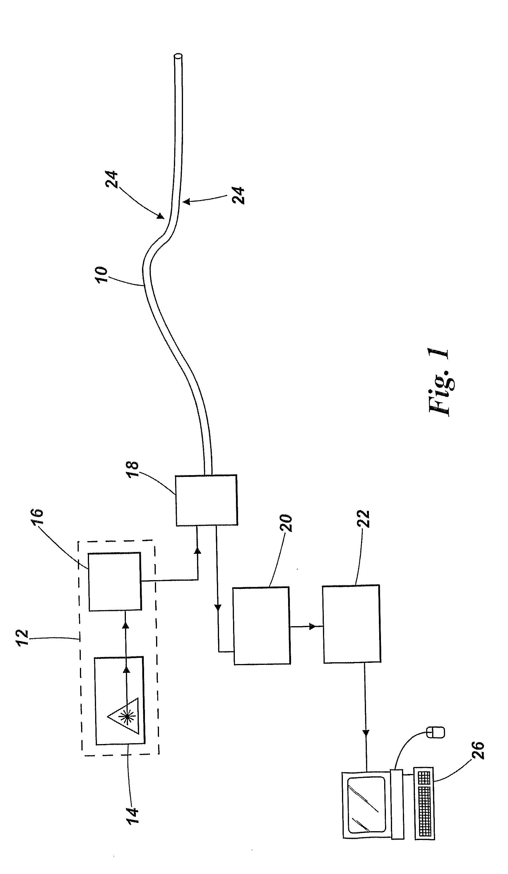
[0035]Referring now to FIG. 1 there is shown a distributed optical fibre sensor embodying the invention. A sensor fibre 10 is deployed in an environment to be sensed, such as along a building structure or down a well bore. The sensor fibre is structured and / or deployed such that it has a birefringence which is responsive to an environmental influence 24. A light source 12 generates pulses of probe light for launching into the sensor fibre, and includes a laser 14 which delivers a laser beam to source optics 16. The source optics 16 conditions the pulses into the desired form and passes them to a fibre coupling 18 for delivery into the sensor fibre.

[0036]As each pulse of probe light travels along the fibre, some of the light is Rayleigh-backscattered from the fibre material, structure and defects. The backscattered light arrives back at the fibre coupling 18 after an interval based on the return optical path length travelled, and is passed to a detector 20 where properties of the bac...


PUM


Abstract

A distributed optical fibre sensor is described. The sensor uses a sensor fibre (10) having a low or zero intrinsic birefringence that is responsive to an environmental parameter (24) such as pressure. Probe light pulses having a diversity of launch polarisation states are used to reduce signal fading and polarisation dependent loss in the retardation beat frequency signals which are sensed (20) and then analysed (22) to determine the environmental parameter as a profile along the sensor fibre.

Description

[0001]The present invention relates to a distributed optical fibre sensor, for example such a sensor that can be used to determine the spatial distribution of environmental influences such as pressure, using the effects of such parameters on the birefringence of a sensor fibre.[0002]Distributed optical fibre sensors are used to measure environmental influences such as static pressure, temperature, mechanical movement, and vibration as a function of position along the length of an extended sensor optical fibre. Typical applications include monitoring conditions in oil, gas, and other well bores, maintaining a check on structures such as pipelines, buildings and bridges, and acoustic monitoring for perimeter security. The basic principle is to launch a laser light pulse into one end of the sensor fibre, to collect light backscattered from along the length of the sensor fibre, to relate the time of flight of collected light to distance of travel and hence position along the sensor fibr...

Claims


Application Information

Patent Timeline
IPC IPC(8): G01D5/353
CPCG01D5/35358G01L1/242
Inventor ROGERS, ALAN JOHN
Owner FOTECH SOLUTIONS
Why Eureka
Try Eureka