Electrical Connector
- Summary
- Abstract
- Description
- Claims
- Application Information
AI Technical Summary
Benefits of technology
Problems solved by technology
Method used
Image

Examples
Embodiment Construction
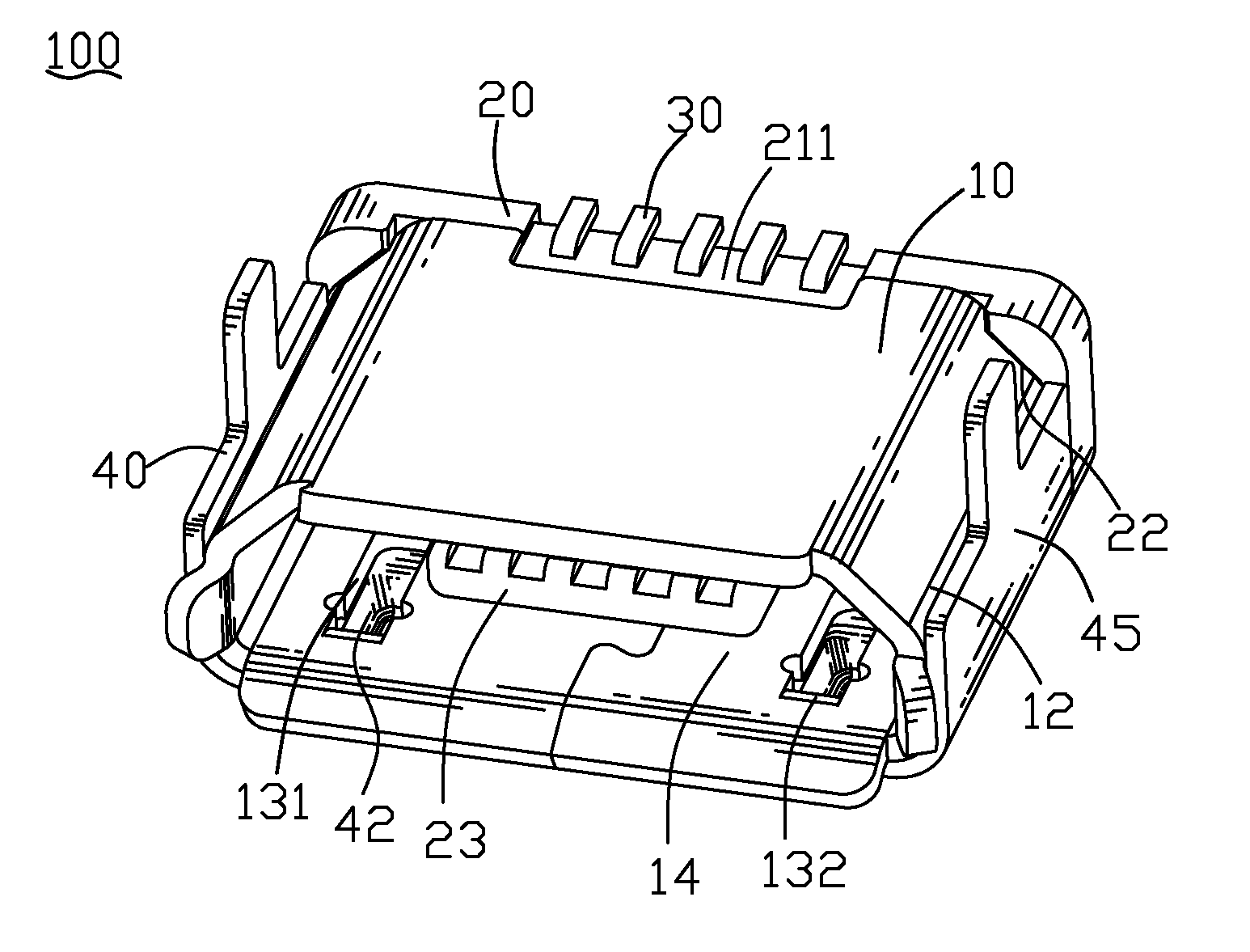
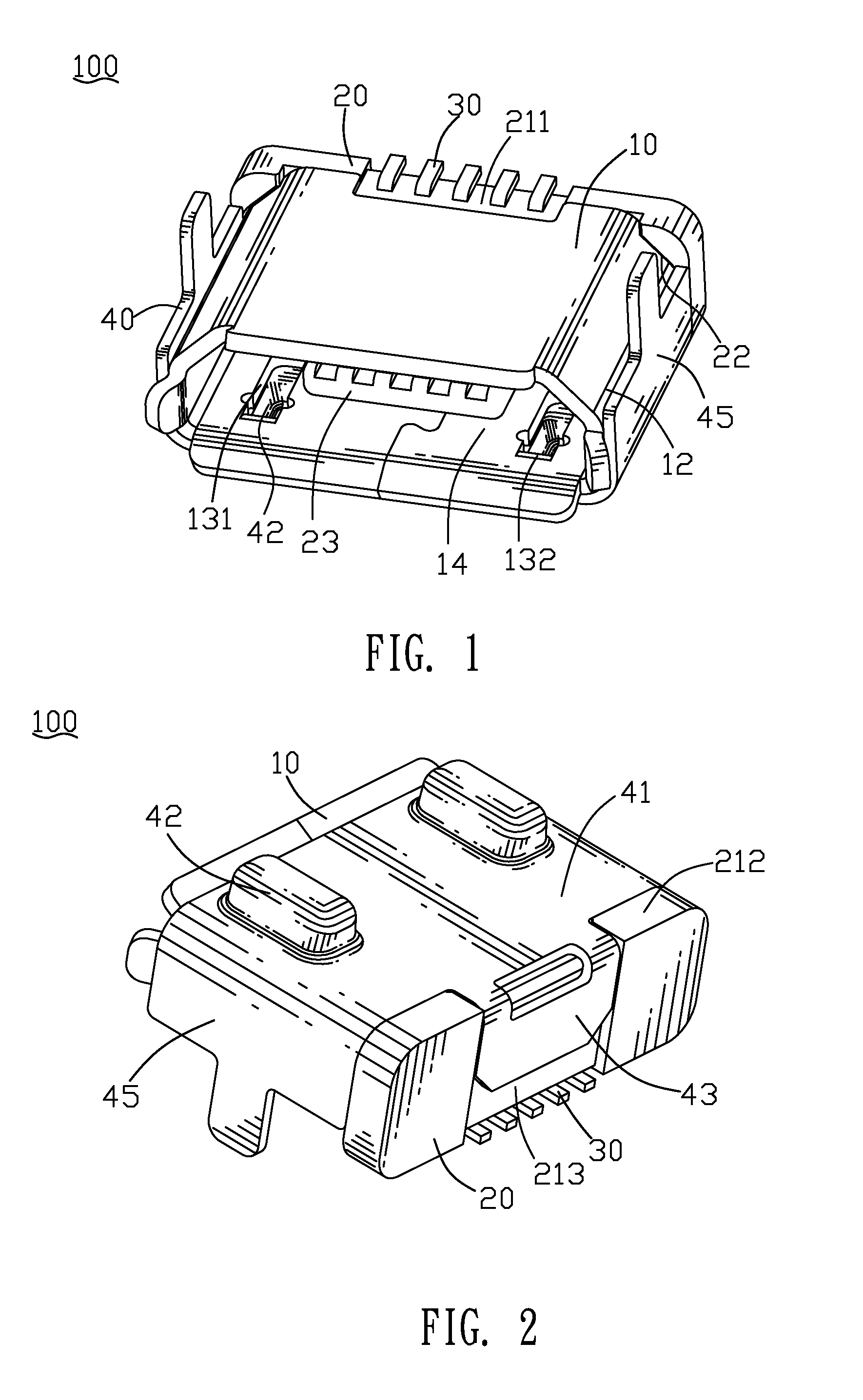
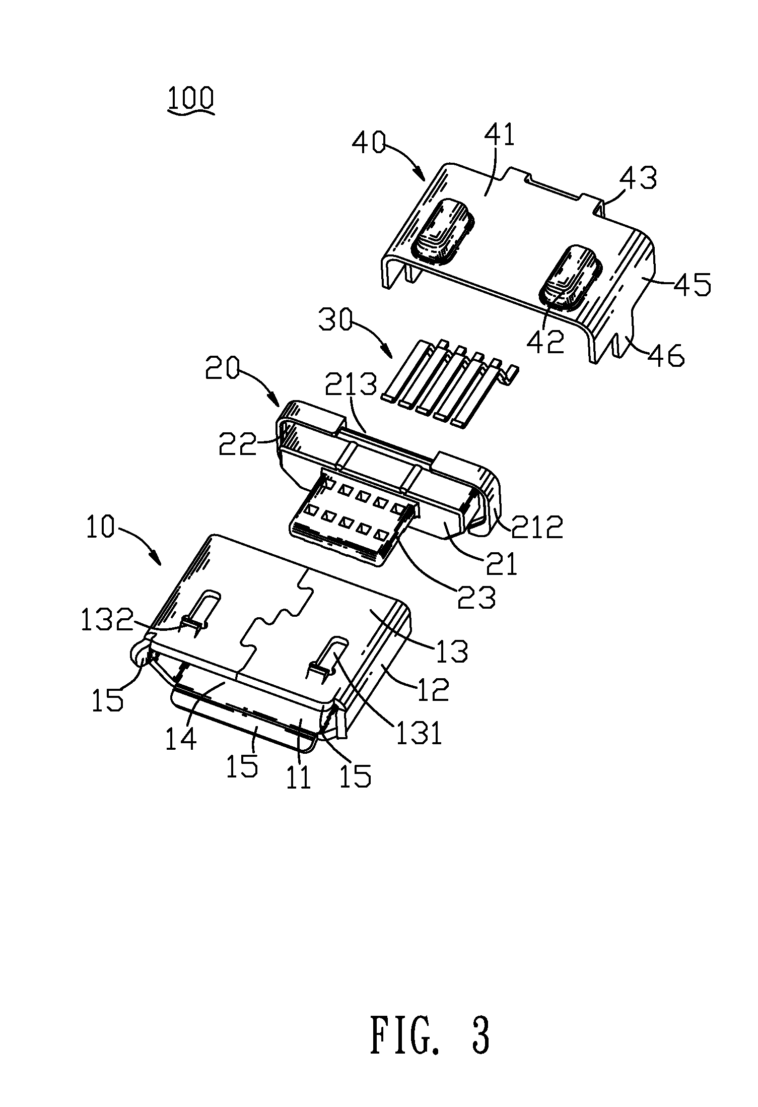
[0013]Referring to FIG. 1 and FIG. 3, an electrical connector 100 according to the present invention includes an inner shell 10, an insulating body 20 engaged with the inner shell 10, a plurality of terminals 30 integrated in the insulating body 20, and an outer shell 40 enclosing the inner shell 10.
[0014]Referring to FIG. 3, FIG. 4 and FIG. 5, the inner shell 10 has a rectangular bottom board 11. Two opposite side edges of the bottom board 11 extend upward to form two side boards 12 facing each other. Two top edges of the side boards 12 are connected by a top board 13. A receiving space 14 is formed among the bottom board 11, the two side boards 12 and the top board 13. Front edges of the bottom, side and top board 11, 12, 13 respectively extend forward and are inclined outward to form a plurality of guiding eaves 15. A middle of a rear edge of the bottom board 11 is concaved inward to form a buckling gap 112. The top board 13 defines two openings 131 at two sides thereof. A front ...
PUM
 Abstract
Description
Claims
Application Information
 - Generate Ideas
- Intellectual Property
- Life Sciences
- Materials
- Tech Scout
- Unparalleled Data Quality
- Higher Quality Content
- 60% Fewer Hallucinations
Browse by: Latest US Patents, China's latest patents, Technical Efficacy Thesaurus, Application Domain, Technology Topic, Popular Technical Reports.
© 2025 PatSnap. All rights reserved.Legal|Privacy policy|Modern Slavery Act Transparency Statement|Sitemap|About US| Contact US: help@patsnap.com