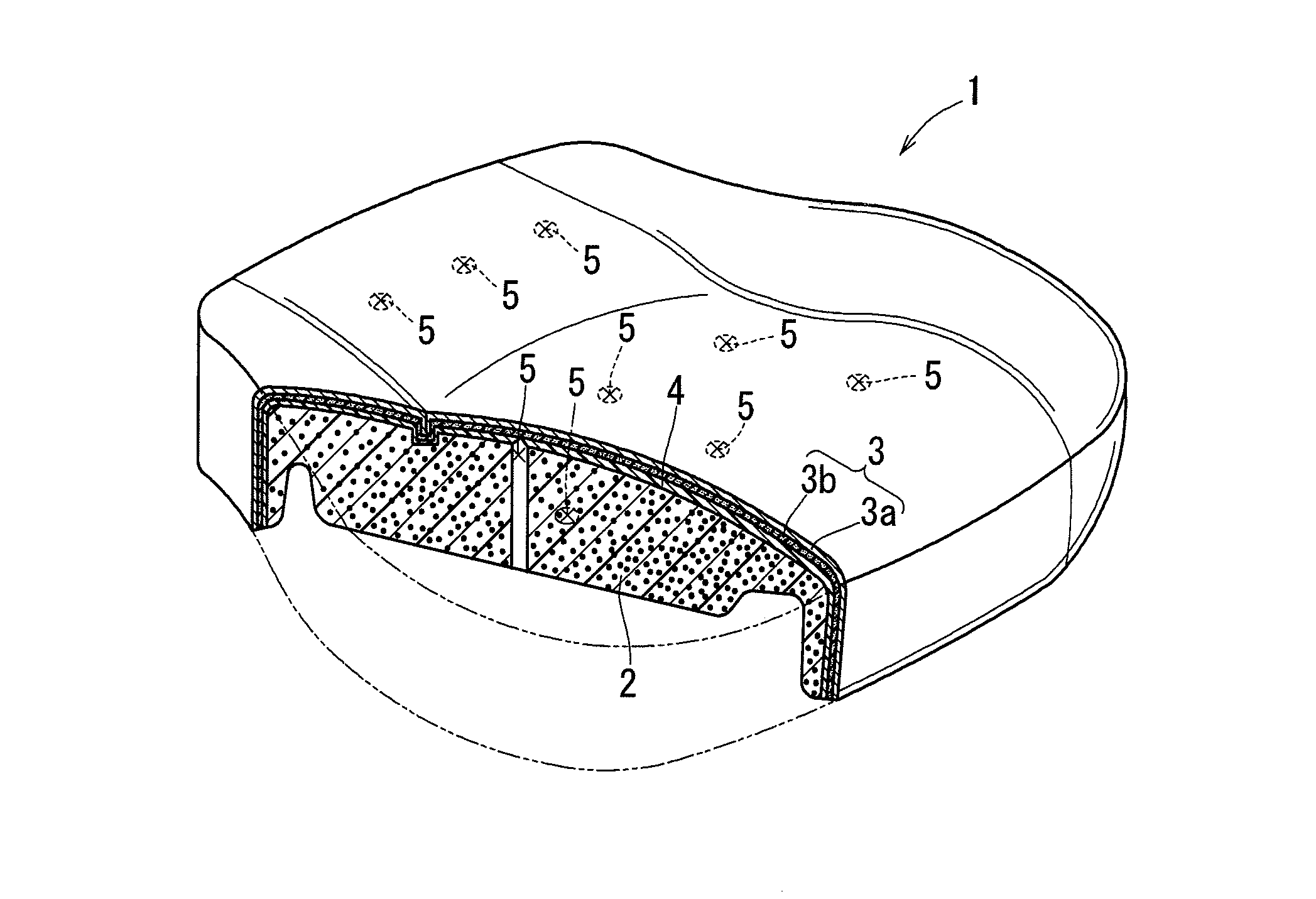
[0008]In the construction of the present invention, the breathing hole is formed in the non-breathable film layer. The breathing hole extends from the back surface side of the breathable pad layer and penetrates the film layer. Thus, each of the
layers may have breathability. The breathing hole is formed while the pad layer and the film layer are melted. Therefore, the breathing hole can be prevented from being closed again, so that a hole shape having a predetermined
diameter can be maintained. Further, the breathing hole extends from the back surface side of the pad layer and penetrates the film layer. Therefore, the breathing hole is invisible from the front surface side. Thus, the breathing hole extends from the back surface side of the breathable pad layer and penetrates the film layer. In addition, the breathing hole is formed while each of the
layers are melted. Therefore, a poor-breathable cushion can be provided with good breathability without deteriorating the appearance thereof.
[0010]In the construction of the present invention, the breathable cushion is used as a cushion member of a seat cushion, a seat back or a headrest of a vehicle seat. Therefore, the vehicle seat is capable of preventing a passenger from getting sweaty. Further, an appearance of the vehicle seat can be prevented from being deteriorated. Thus, the vehicle seat has a good appearance and is capable of preventing a passenger from getting sweaty.
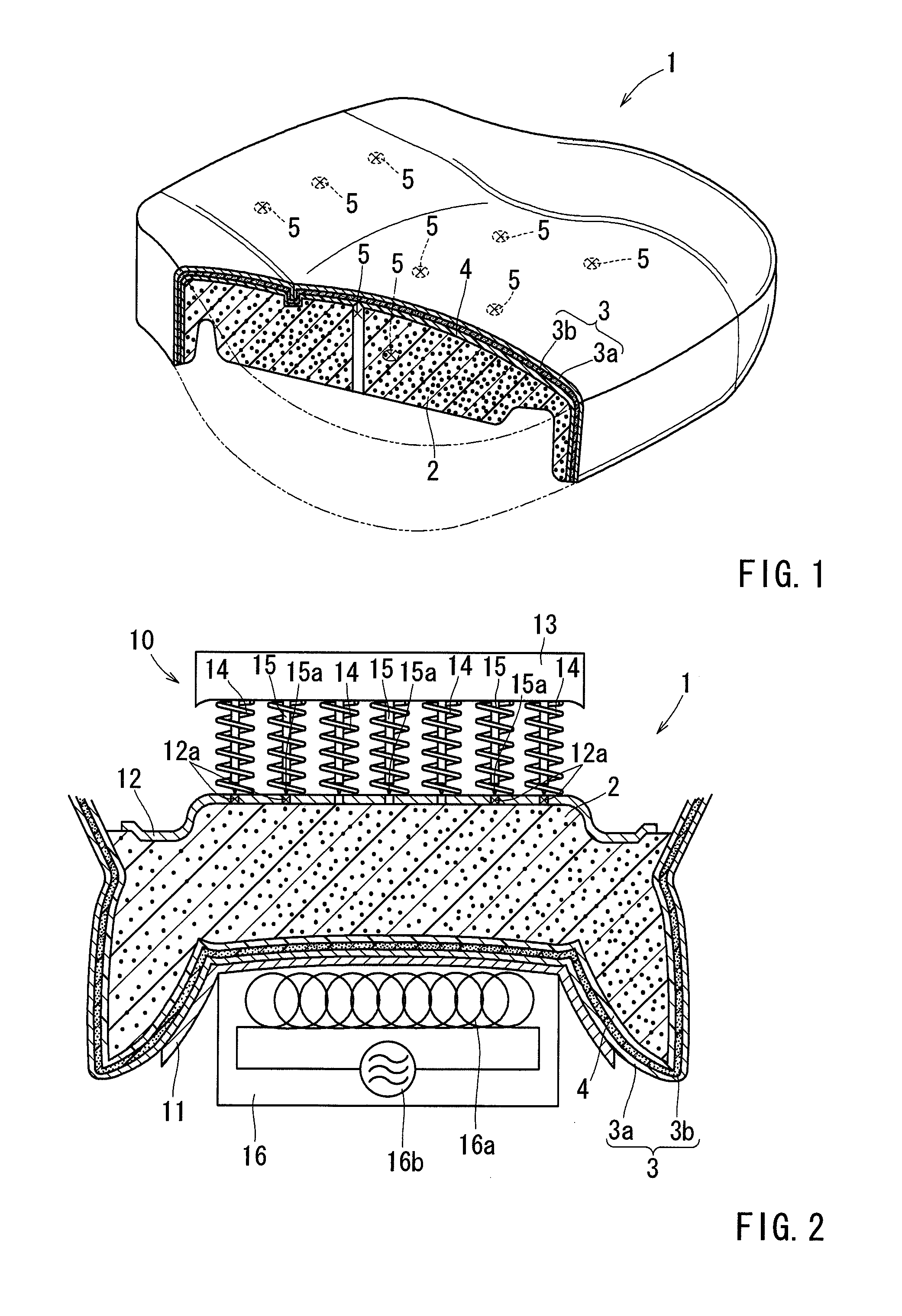
[0012]According to the present invention, in the piercing process, the pre-heated piercing member is pierced into the breathable pad layer from the back surface side thereof to form the breathing hole that penetrates the non-breathable film layer. Thus, each of the
layers may have breathability. The breathing hole is formed while the pad layer and the film layer are melted by the pre-heated piercing member. Therefore, the breathing hole can be prevented from being closed again, so that a hole shape having a predetermined
diameter can be maintained. Further, the breathing hole extends from the back surface side of the pad layer and penetrates the film layer. Therefore, the breathing hole is invisible from a front surface side of the
skin layer. Thus, the breathing hole formed in the piercing process extends from the back surface side of the breathable pad layer and penetrates the film layer. In addition, the breathing hole is formed while each of the layers are melted. Therefore, a poor-breathable cushion can be provided with good breathability without deteriorating the appearance thereof.
[0014]According to the present invention, the piercing member is pre-heated by the
electromagnetic induction heating. Therefore, the piercing member can be remotely heated. Thus, because the piercing member is pre-heated by the
electromagnetic induction heating, the piercing member can be remotely heated easily and quickly.
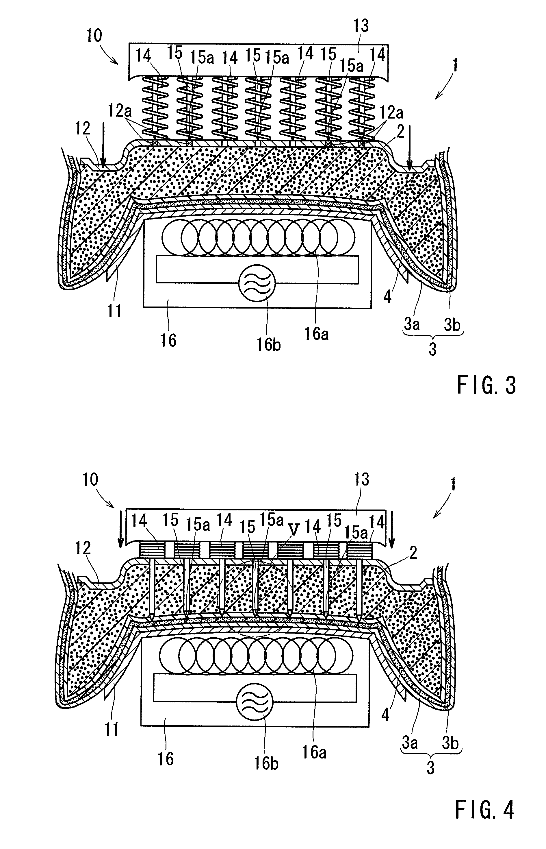
[0015]Further, the present invention can be constructed as follows. That is, a heating coil for generating a magnetic force used in the
electromagnetic induction heating is disposed on a setting die on which the skin layer is set when the piercing process is performed. Further the piercing member is moved toward the heating coil, so as to be pierced into the pad layer from the back surface side thereof. The method further includes a compression process in which the pad layer is compressed and deformed from the back layer thereof toward the front layer thereof before the piercing member is pierced into the pad layer from the back surface side thereof, so as to increase
heating efficiency of the piercing member.
[0016]According to the present invention, in the compression process that is performed before the piercing member is pierced into the pad layer from the back surface side thereof, the piercing member can be positioned closer to the heating coil. As a result, the piercing member can be pierced into the pad layer while efficiently heated by the heating coil. Thus, because the pad layer is compressed and deformed in the compression process prior to the piercing process, the piercing member can be heated by the electromagnetic
induction heating while being positioned closer to the heating coil. As a result, the piercing member can be heated with high
heating efficiency, so that the breathing holes can be reliably formed.

