Thermostatic mixing valve for a domestic heating system

Active Publication Date: 2011-10-27
DEBE FLOW GRP AB
View PDF4 Cites 10 Cited by
  • Summary
  • Abstract
  • Description
  • Claims
  • Application Information

AI Technical Summary

Benefits of technology

[0007]The above problems have been solved by a thermostatic mixing val

Problems solved by technology

However, the known valve has proven less suitable for smaller heating arrangements with a rated output up to 30 kW.
In such relatively small plants the relatively low fluid flow rate and, in some cases, relatively large pressure differences in the fluid system the known valve may exper

Method used


Image

  • Thermostatic mixing valve for a domestic heating system
  • Thermostatic mixing valve for a domestic heating system
  • Thermostatic mixing valve for a domestic heating system

Examples


Embodiment Construction

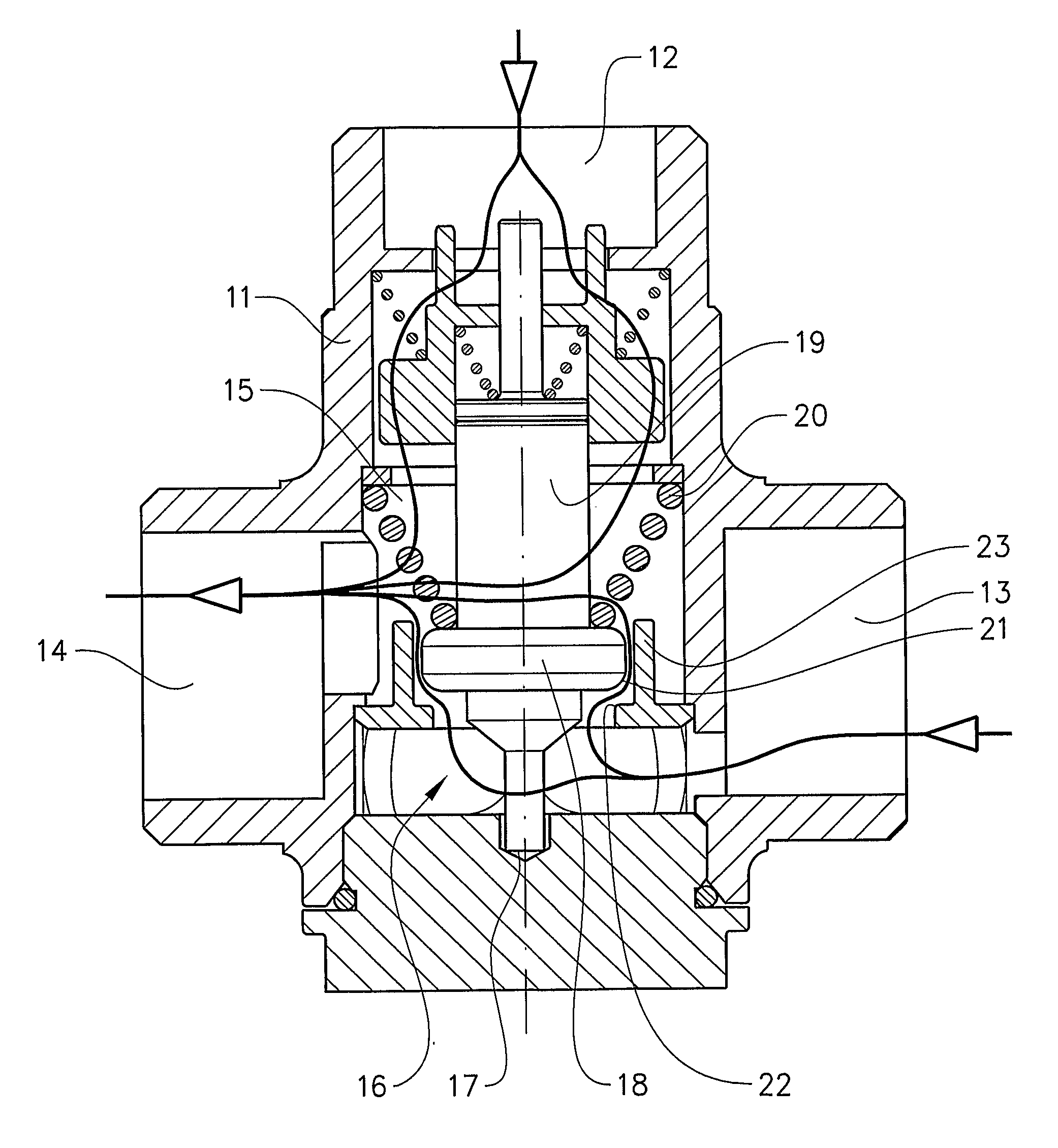
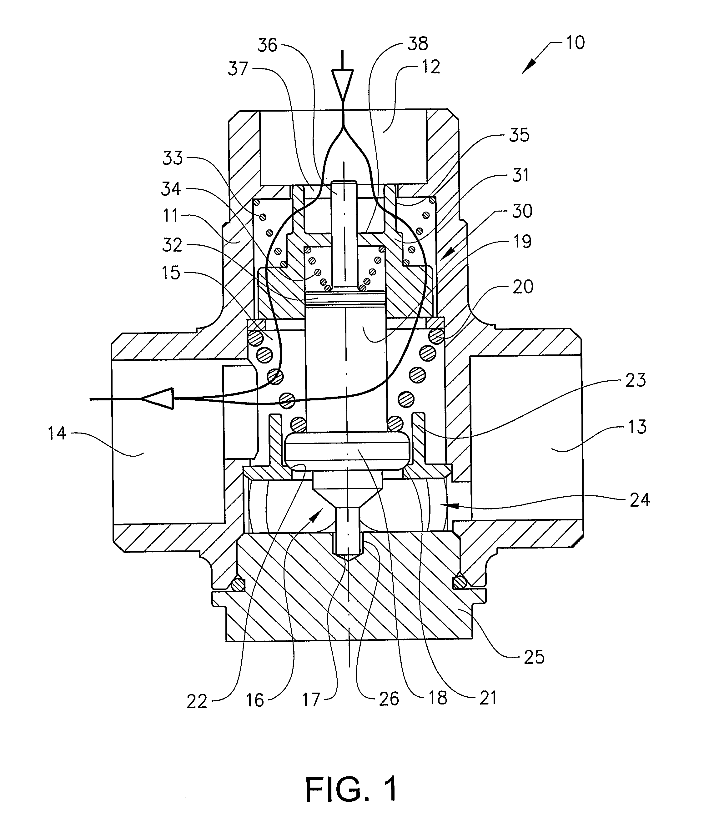
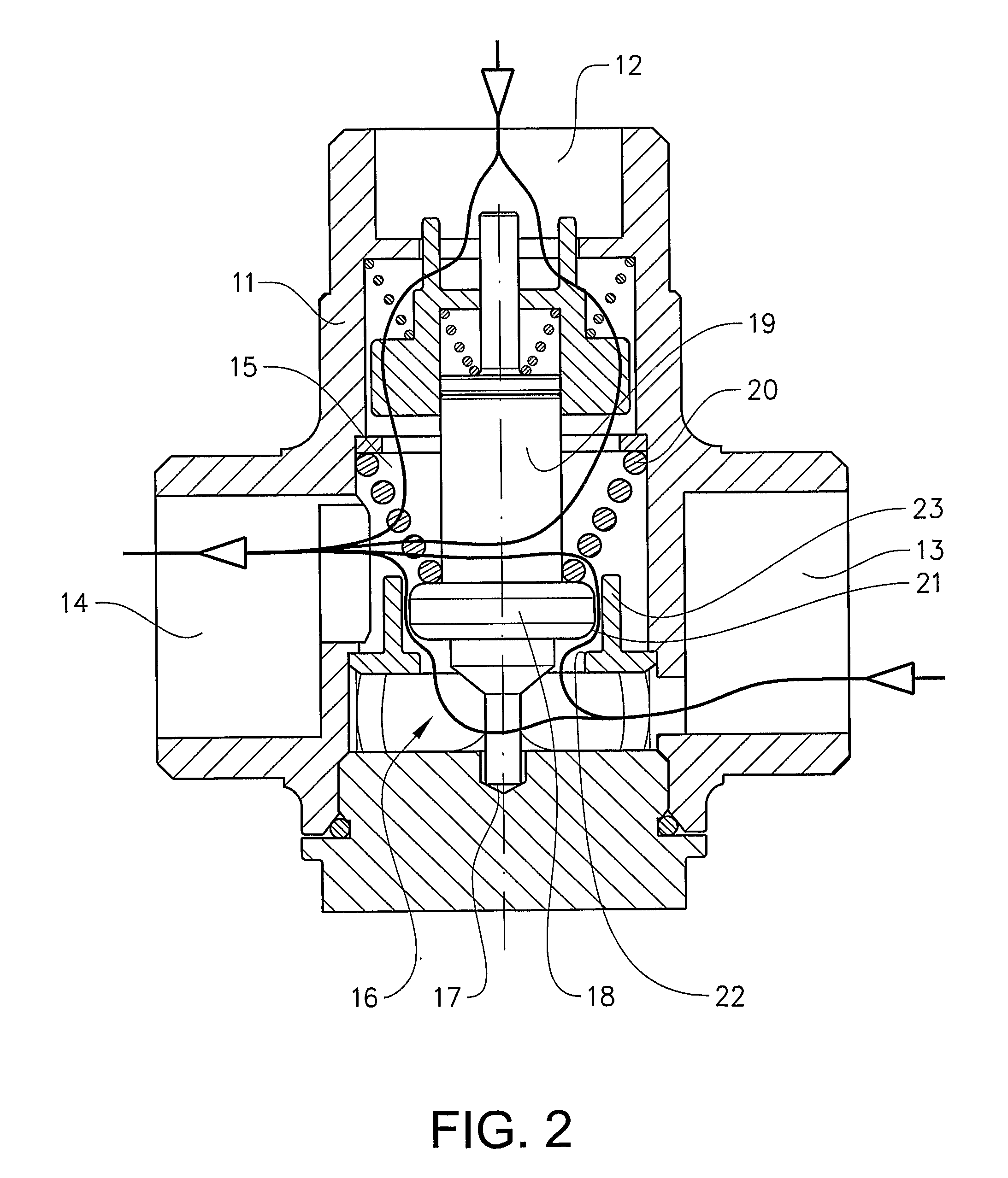
[0023]FIGS. 1-3 show a schematic cross-section of a thermostatic mixing valve 10 according to the invention.

[0024]The thermostatic mixing valve 10 comprises a hollow body 11 with a cavity having a first inlet 12 and a second inlet 13 for water from separate sources, and an outlet 14 for mixed water. The outlet 14 is in fluid communication with the first inlet 12 and / or the second inlet 13 via a mixing chamber 15. The hollow body 11 is further provided with an axially extending thermostatic actuator 16 comprising a stem 17, an enlarged portion 18 and a heat sensitive bulb 19, said bulb extending into the mixing chamber 15.

[0025]The thermostatic actuator 16 is arranged to be axially displaced between a first end position in which only the first inlet 12 is connected to the outlet 14 and a second end position in which only the second inlet 13 is connected to the outlet 14. When the thermostatic actuator 16 is located in any position between the first and second end positions, water flo...


PUM


Abstract

The invention relates to a thermostatic mixing valve comprising a hollow body having a first inlet, a second inlet, and an outlet in fluid communication with the first inlet and/or the second inlet via a mixing chamber. The flow through the valve is controlled by an axially extending thermostatic actuator comprising a stem, an enlarged portion and a heat sensitive bulb, said bulb extending into the mixing chamber. The thermostatic actuator is axially displaced between a first end position in which only the first inlet is connected to the outlet and a second end position in which only the second inlet is connected to the outlet. The thermostatic actuator is displaced in a sleeve member arranged to restrict the flow of water from the second inlet past the enlarged portion of the thermostatic actuator during its axial displacement until the thermostatic actuator reaches the second end position.

Description

CROSS-REFERENCE TO RELATED APPLICATIONS[0001]This application is based on PCT / SE2008 / 000471, filed Aug. 15, 2008, the contents of which are incorporated by reference.TECHNICAL FIELD[0002]The present invention relates to a thermostatic mixing valve and a domestic heating arrangement using such a valve.BACKGROUND[0003]In domestic heating arrangements utilising an accumulator means for temporary storage of a heated fluid, such as water, some form of heating arrangement is used for heating the fluid in the accumulator means. For instance, when using a water heating boiler for heating the water in an accumulator tank it is desirable to heat the water in the boiler to a predetermined temperature before charging the accumulator tank with hot water. Once the water circulating in the boiler has reached a predetermined temperature, a thermostatic mixing valve connecting the boiler and the accumulator tank is actuated to initiate a relatively slow charging of the accumulator tank. A slow charg...

Claims


Application Information

Patent Timeline
IPC IPC(8): G05D11/00
CPCF16K11/044F16K31/002G05D23/134F24D19/1024F24D11/004Y10T137/2499
Inventor THOMASSON, ANDERS
Owner DEBE FLOW GRP AB
Why Eureka
Try Eureka