Axial fan

a technology of axial fans and fans, applied in the direction of machines/engines, liquid fuel engines, other chemical processes, etc., can solve the problem of electrical parts being thermally destroyed, and achieve the effect of increasing air volum

Active Publication Date: 2011-10-27
MINEBEAMITSUMI INC
View PDF7 Cites 12 Cited by
  • Summary
  • Abstract
  • Description
  • Claims
  • Application Information

AI Technical Summary

Benefits of technology

[0008]The present invention has been made in view of the above problems, and it is an aspect of the present invention to provide an axial fan having improved flow rate characteristic by improving a blade shape of the axial fan.
[0011]According to the above configuration, it is possible to provide an axial fan having the stable and improved static pressure—flow rate characteristic and capable of improving the static pressure—flow rate characteristic.
[0013]According to the above configuration, it is possible to provide an axial fan capable of further improving the static pressure—flow rate characteristic without deteriorating it due to a surging phenomenon and the like.
[0015]According to the above configuration, it is possible to improve the flow rate characteristic by gently guiding the air of the inlet port into the cylindrical casing and guiding the air having passed through the cylindrical casing toward the outlet port.
[0017]According to the above configuration, it is possible to improve the flow rate characteristic by guiding the air having passed through the cylindrical casing toward the outlet port and by increasing the pressure at the outlet port.
[0019]According to the above configuration, since it is possible to use, as the inlet port, the slit or the hole formed in the sidewall of the cylindrical casing, it is possible to further increase the air volume.

Problems solved by technology

Therefore, heat that is generated from the electronic parts is confined in the casing, so that the electronic parts can be thermally destroyed, which causes considerable problems.

Method used


Image

  • Axial fan
  • Axial fan
  • Axial fan

Examples


Embodiment Construction

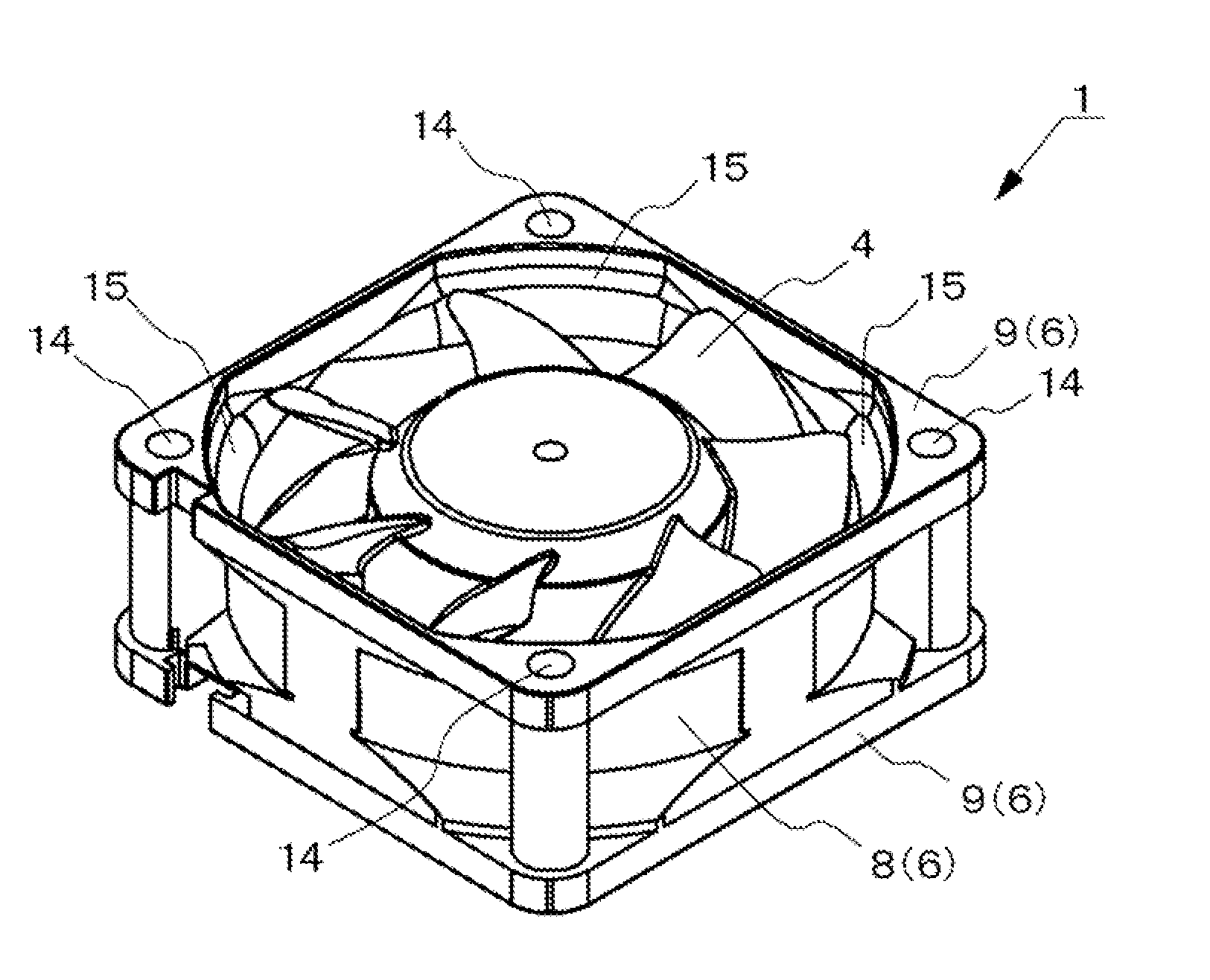
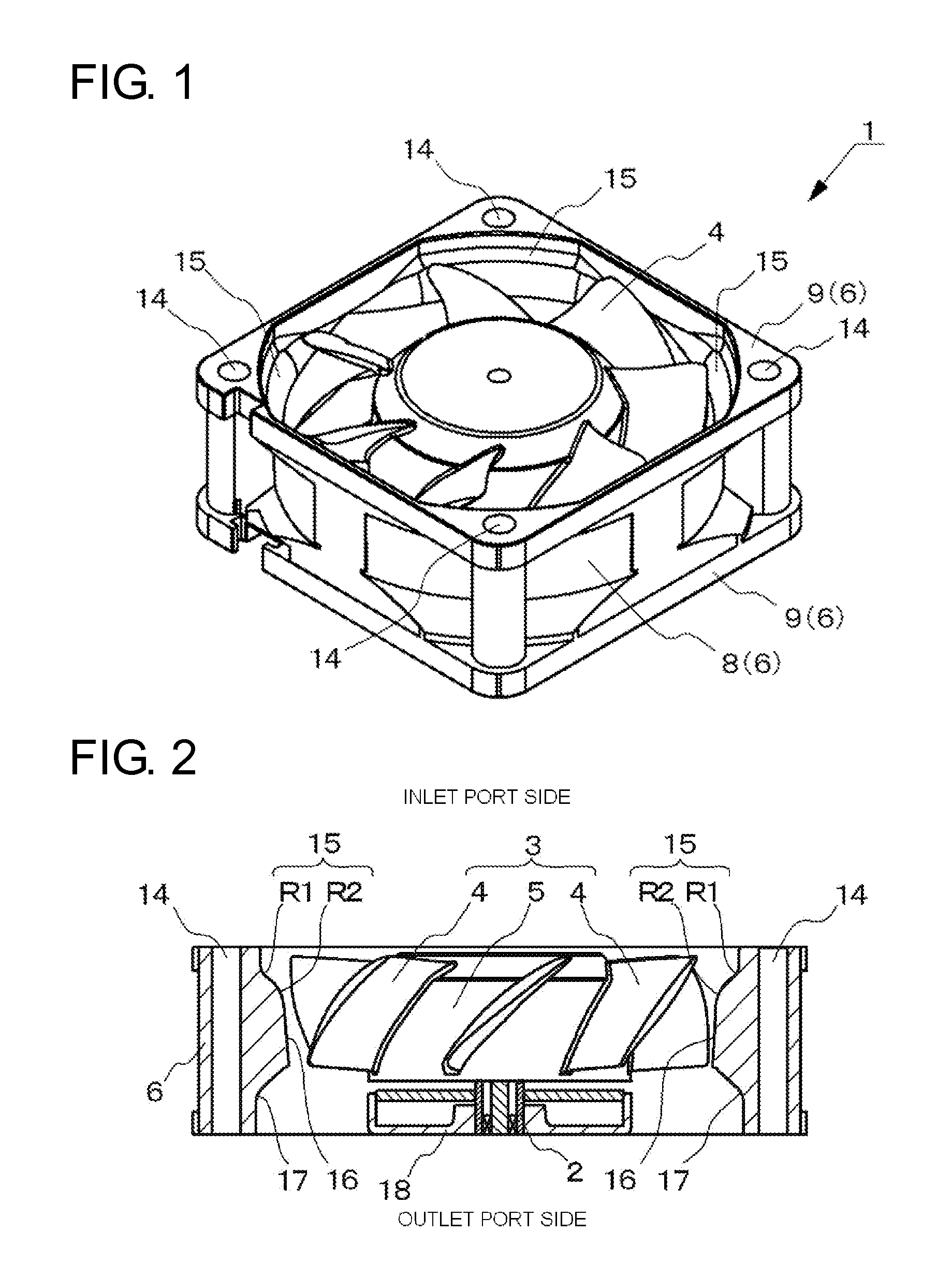
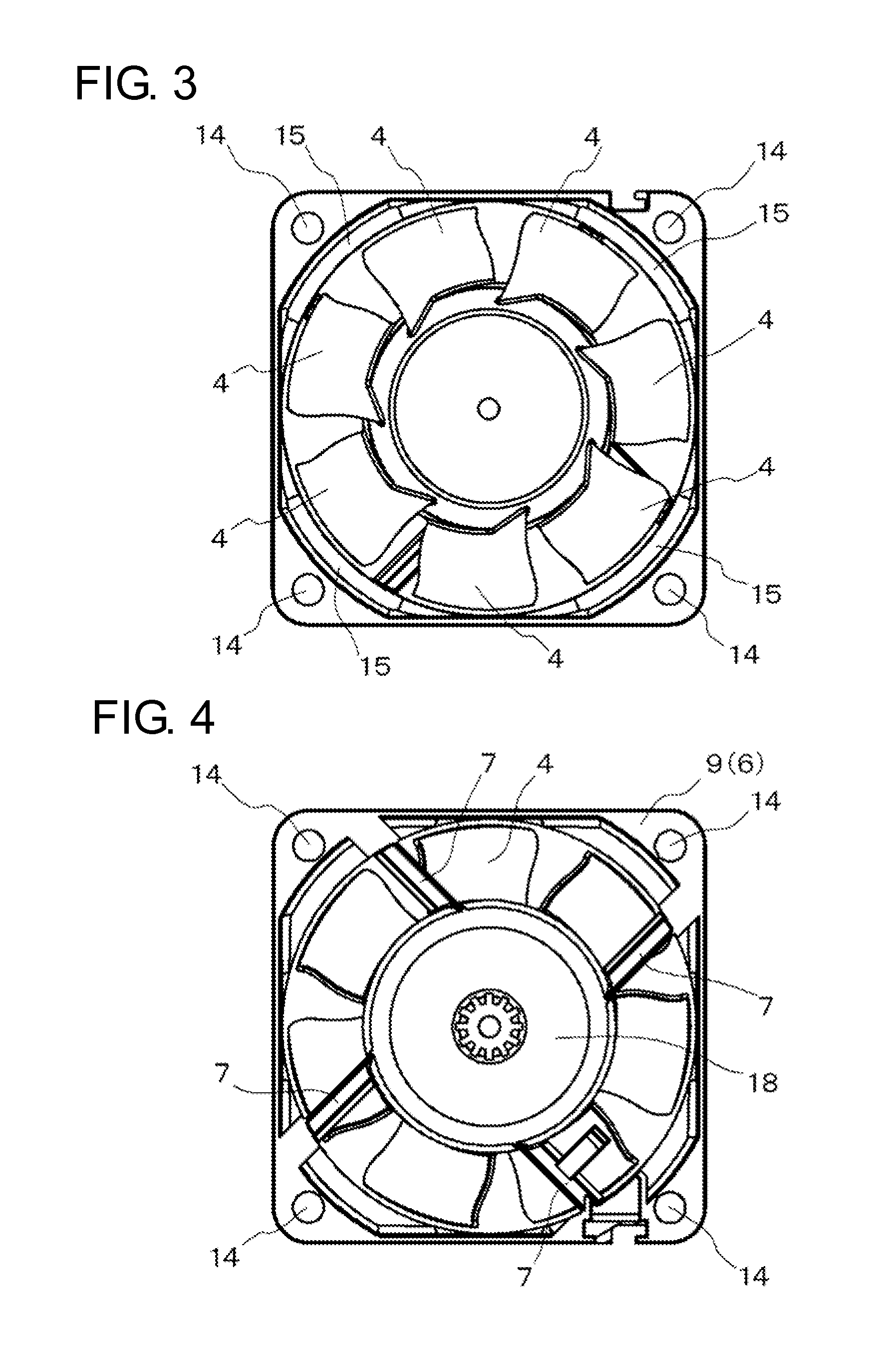
[0035]Hereinafter, illustrative embodiments of the present invention will be described with reference to the drawings. FIG. 1 is a perspective view showing an axial fan according to an illustrative embodiment of the present invention, FIG. 2 is a sectional view of FIG. 1, FIG. 3 is a plan view seen from an inlet side of the axial fan shown in FIG. 1, FIG. 4 is a bottom view of the axial fan shown in FIG. 1, FIG. 5 is a perspective view of an impeller shown in FIG. 1, FIG. 6 is a plan view of the impeller shown in FIG. 5, which illustrates a front-edge angle of a blade, FIG. 7 illustrates a relation between the front-edge angle of the blade and a flow rate, FIG. 8 is a side view of the impeller shown in FIG. 5, which illustrates a mounting angle of a blade, FIG. 9 illustrates a relation between the mounting angle of the blade and a flow rate, FIG. 10 illustrates a twisted angle of a blade and FIG. 11 illustrates a relation between the twisted angle of the blade and a flow rate. It is...


PUM


Abstract

An axial fan is provided. The axial fan includes a hub, an impeller having a plurality of blades mounted on an outer peripheral surface of the hub, and a housing surrounding the impeller. Each of the blades has a front edge angle (α) within a range of −8° to −20°, a mounting angle (β) within a range of 36° to 50°, and a twisted angle (θ) within a range of 10°±2°.

Description

BACKGROUND OF THE INVENTION[0001]1. Field of the Invention[0002]The present invention relates to an axial fan, and more particularly, to an axial fan that is used to cool an electronic device and the like.[0003]2. Description of the Related Art[0004]For example, in electronic devices such as personal computer, copier and the like, a plurality of electronic parts is housed in a relatively small casing. Therefore, heat that is generated from the electronic parts is confined in the casing, so that the electronic parts can be thermally destroyed, which causes considerable problems. Accordingly, vent holes are formed in a wall surface or ceiling surface of the casing of the electronic device, so that the heat in the casing is radiated through the vent holes. In the meantime, an axial fan is used as a cooling means of the electronic device. The axial fan for cooling the electronic device is required to reduce noise as much as possible and to improve an air volume (flow rate) performance. ...

Claims


Application Information

Patent Timeline
Patent Type & Authority Applications(United States)
IPC IPC(8): F04D19/00
CPCY10S416/02F04D29/384
Inventor FUKUDA, TAKAKOOGUSHI, MASAKIKAWAI, YOICHIOHKI, NAOYA
Owner MINEBEAMITSUMI INC
Why Eureka
Try Eureka