Solar thermal collecting system

a solar thermal and collecting system technology, applied in the field of solar energy, can solve the problems of gas enclosure breakage and increase the risk, and achieve the effect of increasing the available volum

Active Publication Date: 2011-11-03
TIGI
View PDF26 Cites 8 Cited by
  • Summary
  • Abstract
  • Description
  • Claims
  • Application Information

AI Technical Summary

Benefits of technology

[0007]It is provided according to some embodiments of the present invention a solar energy module for converting solar light to thermal energy. The module includes a thermally insulating element transmissive to solar radiation and having low transmissivity to thermal infra-red radiation, an absorbing element for absorbing the solar radiation, a sealed enclosure associated with the absorbing element, and a variable portion in the envelope of the sealed enclosure. This portion is adapted for varying the volume available to gas enclosed in the enclosure in accordance with changing temperature of the enclosed gas. Solar radiation penetrates the thermally insulating element and is absorbed by the absorbing element. As a result, the enclosed gas is heated and the variable portion varies to increase the available volume. Thus pressure of enclosed gas is kept within structurally tolerable limits and can in principle enable pressure equilibration with the external environment.

Problems solved by technology

The sealing of the insulative panel however, creates new challenges, related to pressure build up and the risk of catastrophic breakdown of the gas enclosure.
This risk is exacerbated by the increased volume of the solar panel due to the inclusion of transparent insulating panel, together with the wider range of temperature fluctuation enabled by the transparent insulation.

Method used


Image

  • Solar thermal collecting system
  • Solar thermal collecting system
  • Solar thermal collecting system

Examples


Embodiment Construction

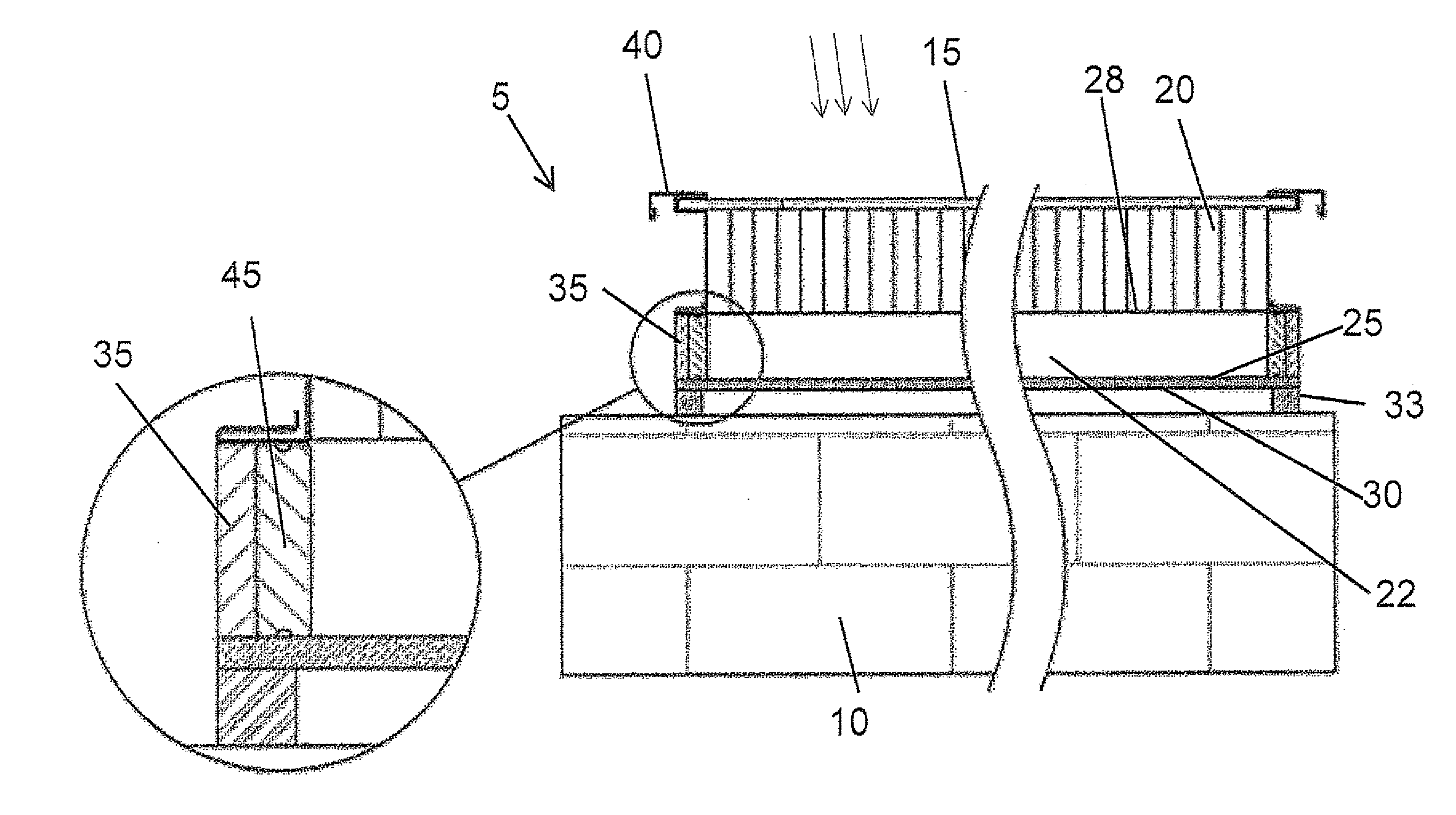
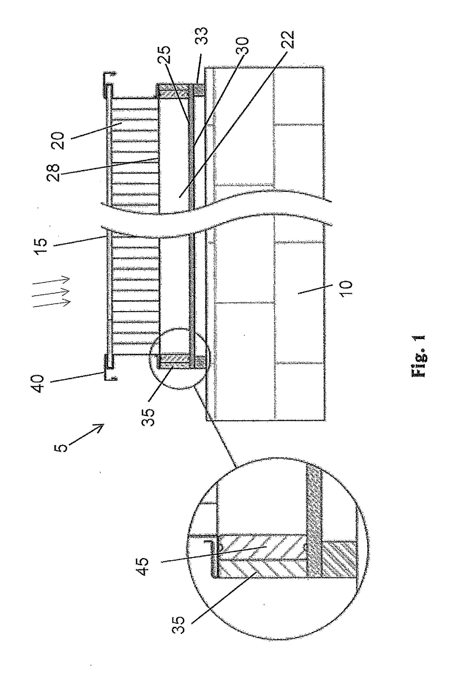
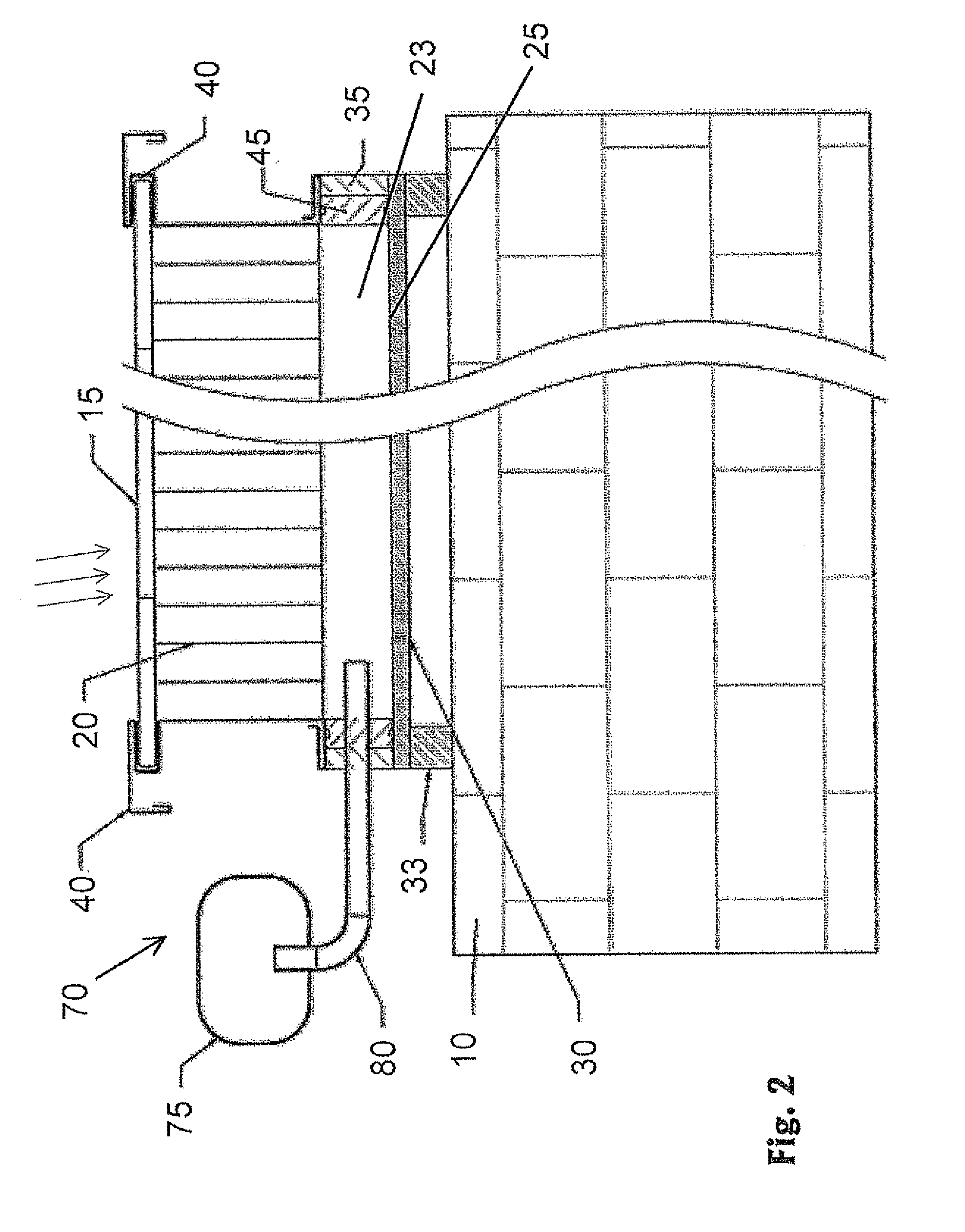
[0030]The present invention will now be described in terms of specific examples of embodiments. It is to be understood that the invention is not limited to the example embodiments disclosed. It should also be understood that not every feature of the methods and systems handling the described system is necessary to implement the invention as claimed in any particular one of the appended claims. Various elements and features of the system are described to fully enable the invention. It should also be understood that throughout this disclosure, where a method is shown or described, the steps of the method may be performed in any order or simultaneously, unless it is clear from the context that one step depends on another being performed first.

[0031]Before explaining several embodiments of the invention in detail, it is to be understood that the invention is not limited in its application to the details of construction and the arrangement of the components set forth in the following des...


PUM


Abstract

It is provided a solar energy module for converting solar radiation to thermal energy. The module includes a thermally insulating element transmissive to solar radiation and having low transmissivity to thermal infra-red radiation, an absorbing element, a sealed enclosure, and a variable portion in the envelope of the sealed enclosure. This portion is adapted for varying the volume available to gas enclosed in the enclosure in accordance with changing temperature of the enclosed gas. Also, it is provided a solar energy module which includes a thermally insulating element, an absorbing surface and liquid pipes for absorbing the solar radiation, and an air duct thermally coupled thereof. The heated liquid and the heated air are usable for a variety of thermal applications. A heat storage may be thermally coupled to the absorbing surface and to the liquid pipes. The air duct has several air valves, and is associated with a controller for regulating air flow through the air duct. The controller may regulate heat flow in accordance with an optimization program, receiving inputs from several sources, like a sensor monitoring a building, a sensor monitoring the solar energy module, and an environment sensor.

Description

BACKGROUND OF THE INVENTION [0001]1. Field of the Invention[0002]The invention is in the field of solar energy, and in particular deals with solar energy modules with pressure controlled gas enclosures, controlled air duct, and means for distributing solar energy to a variety of building applications.[0003]2. Description of Related Art[0004]Thermally insulating panel transmissive to solar radiation, while having low transmissivity to thermal infra-red radiation, had been disclosed in U.S. Pat. No. 4,480,632, U.S. Pat. No. 4,719,902, U.S. Pat. No. 4,815,442, U.S. Pat. No. 4,928,665 and U.S. Pat. No. 5,167,217 all to Klier and Novik. The thermally insulating panel, also called transparent insulation material or thermal diode may be a honeycomb made of synthetic material or glass which is transparent to solar IR and visible wavelength, and opaque to thermal IR back-radiation, as a result of the optical properties of the material and its geometry. At the same time the transparent insula...

Claims


Application Information

Patent Timeline
Patent Type & Authority Applications(United States)
IPC IPC(8): F24J2/04F24J2/46F24J2/40F24J2/50F24S90/00
CPCF24J2/34F24J2/505Y02E10/40Y02B10/20F24J2/515F24S40/80F24S60/30F24S80/52F24S80/54F24S80/65Y02P90/50F24S50/00F24S80/45
Inventor KLIER, SHIMONADEL, MICHAEL
Owner TIGI
Why Eureka
Try Eureka