Weaving Machine and Method for Three-Dimensional Weaving

Inactive Publication Date: 2011-11-03
GROZ BECKERT KG
View PDF16 Cites 15 Cited by
  • Summary
  • Abstract
  • Description
  • Claims
  • Application Information

AI Technical Summary

Benefits of technology

[0014]Preferably, the lamellae are located on a common bar. The lamellae are arranged on the bar so that they can be shifted in the direction of their extension. In this manner, the desired weft thread path may be adjusted very easily by shifting the lamellae relative to each other. The position of the lamellae can be changed after each weft thread entry. As a result of this, three-dimensional fabric forms with continuous transitions can be created. In the exemplary embodiment, the lamellae and the bar form the reed of the weaving machine. In order to cast on the weft thread, the reed is pivotally supported. Consequently, the lamellae are not only disposed to define the weft thread path but, at the same time, for casting on the weft thread at the fabric edge.

Problems solved by technology

This process is time-consuming and expensiv

Method used


Image

  • Weaving Machine and Method for Three-Dimensional Weaving
  • Weaving Machine and Method for Three-Dimensional Weaving
  • Weaving Machine and Method for Three-Dimensional Weaving

Examples


Embodiment Construction

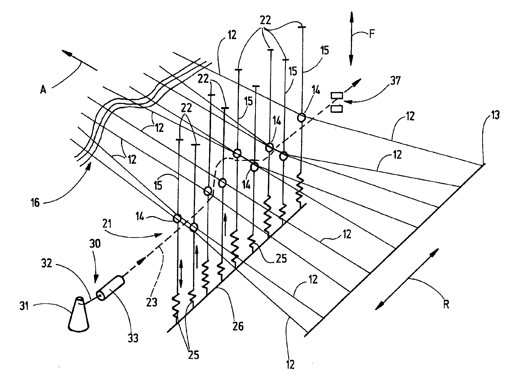
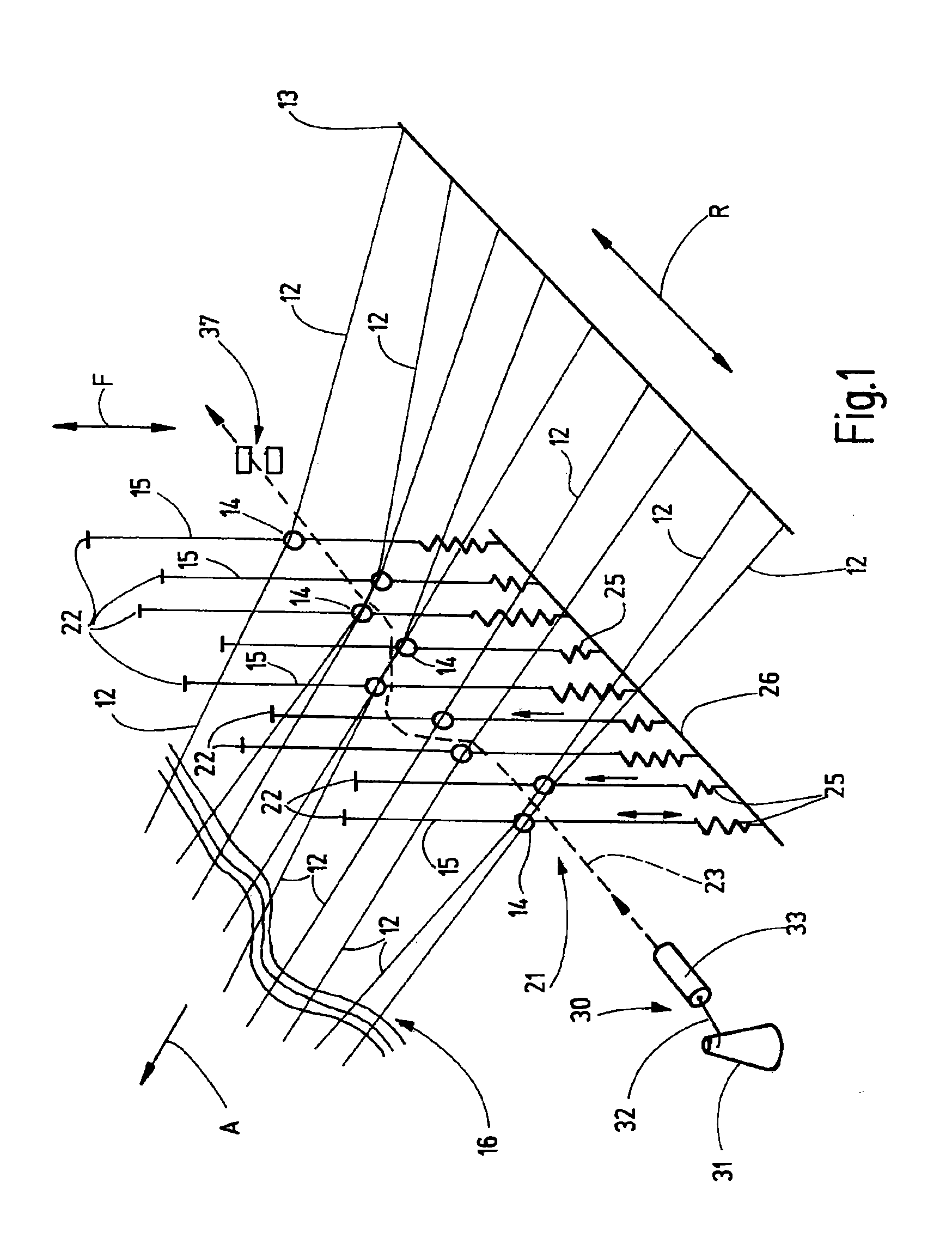
[0025]FIGS. 4 and 5 show a weaving machine 10 in the manner of a block diagram. The weaving machine 10 comprises a spool rack 11 by way of which the weaving machine 10 is supplied with warp threads 12. A holding rack 13 orders the warp threads 12 into one input direction R (FIG. 1), uniformly next to each other. Starting from the holding rack 13, each warp thread 12 extends through a thread eye 14 of a heald 15. The warp threads 12 further extend to a fabric edge 16 where the already woven, finished fabric ends. A draw-off device 17 pulls off the already produced fabric and, in doing so, ensures the transport of the warp thread 12 in draw-off direction A of the weaving machine 10. In the exemplary embodiment, the draw-off device 17 comprises several draw-off rollers 18 across the entire fabric width in input direction R, said draw-off rollers being able to form one or more pairs of rollers that can be resiliently pressed against each other. One or more of the draw-off rollers are dr...


PUM


Abstract

a weaving machine and a weaving method for direct three-dimensional weaving, wherein the weft thread (32) is imparted with its desired two-dimensional course already when the weft thread is being input. The position of the warp threads (12) is adapted to the weft thread path (23). The weft thread path (23) is defined by the lamellae (44) that extend into the shed (21) in between the warp threads (12). The lamellae (44) are arranged on a common bar (45) so that they can be individually adjusted, thus enabling the adjustment of the desired weft thread path (23) by positioning the lamellae (44). The lamellae (44) and the bar (45), at the same time, form the reed (43) that is used for casting on the weft thread (32) at the fabric edge (16).

Description

CROSS-REFERENCE TO RELATED APPLICATION[0001]The present application claims the priority of European Patent Application No. 10 161 488.1, filed Apr. 29, 2010, the subject matter of which, in its entirety, is incorporated herein by reference.BACKGROUND OF THE INVENTION[0002]The invention relates to a weaving machine and a method for three-dimensional weaving. Woven fabrics are a frequently used as reinforcing means in composite materials. In doing so, the fabric fibers are preferably subject to tensile loading. Referring to three-dimensionally formed components such as occur in automobile or ship body construction, the fabric incorporated in the composite material must be adapted to the desired component form.[0003]This may be accomplished, for example, in that the whole fabric is cut into individual pieces that are then arranged so as to overlap on the three-dimensional component and are then incorporated by lamination. This process is time-consuming and expensive. Therefore, it has ...

Claims


Application Information

Patent Timeline
IPC IPC(8): D03D41/00D03C13/00D03C9/00D03D3/00
CPCD03D41/004D03D25/005D03D47/278
Inventor KUHL, THOMASDURST, FRANKFEHRENBACHER, ECKHARD
Owner GROZ BECKERT KG
Why Eureka
Try Eureka