Six-Wheeled Strecher

a stretcher and six-wheel technology, applied in the field of six-wheeled stretchers, can solve the problems of obstructing the application of brakes, insufficient improvement, and inability to smoothly move to lay the stretcher alongside the bed, so as to achieve rapid reception and transportation, facilitate the effect of performing and effectively transporting

Inactive Publication Date: 2011-11-03
MATUNAGA MANUFACTORY
View PDF28 Cites 44 Cited by
  • Summary
  • Abstract
  • Description
  • Claims
  • Application Information

AI Technical Summary

Benefits of technology

[0028]The rear ends of the support arms are axially attached to the lower ends of the rear auxiliary legs, the link operation parts for supporting the rotatable casters are axially attached to front ends of the support arms, the rotatable casters and the lower ends of the rear legs are axially attached to the link operation parts and the rear auxiliary legs can vertically hold axes of the rotatable casters through the rear legs and the support arms. When the height of the six-wheeled stretcher is changed from the highest position to the intermediate position, transfer from the bed to the stretcher and from the stretcher to the bed can be rapidly achieved. At the intermediate position or the lowest position, the rotatable auxiliary casters of the front legs contact the ground and the six-wheeled stretcher rotates. Both of front wheels and rear wheels of the stretcher can rotate with a short turning radius, and therefore, reception and transport can be rapidly achieved. In addition, at the lowest position, lifesaving treatment such as cardiac massage can be easily performed and the patient can be effectively transported at a safe position.
[0029]By providing the constant force springs or tension spring members as the slide mechanisms provided to reduce loads in vertical movement of the stretcher, the constant force springs or the spring members reduce the loads generated by vertically moving the stretcher. The strength of the loads can be easily changed by using different springs having different diameters, thickness and lengths.
[0030]Further, by attaching the spring covers to the spring members, it is possible to prevent metal sound that the spring members generate when expanding or contracting. It is also possible to prevent metal sound that the spring members generate when hitting against the center rail and the like of the stretcher. Furthermore, it is possible to prevent clothes of the patient and a medical bandage from being caught by the spring members.
[0031]By providing the brake mechanisms at the rotatable rear casters, when the six-wheeled stretcher is set to the lowest position, the upper frame contacts the brake mechanisms, automatically applying brakes on the rear casters, and thus, there never occurs forgetting to brake. Further, even when the six-wheeled stretcher according to the present invention is set to the lowest position and receives the patient on the slope land, since the rotatable rear casters of the six-wheeled stretcher are automatically fixed, the operation of receiving the patient can be performed in safety.
[0032]By providing the tiltable handle arm that can be bent and stored under a bed when unnecessary at the rear of the stretcher, when the stretcher is moved in the low state after treatment such as cardiac massage, the handle arm can be raised and used to pull or push the stretcher. Further, since the stretcher can be rapidly transported in case of emergency with the handle arm being bent and pulled, loads are not applied to the lower back of the ambulance crew.
[0033]By attaching the stoppers for preventing rotation of the rotatable auxiliary casters, the stretcher can be fixed at the low position. By fixing the stretcher, advantageously, the ambulance crew can place the patient on the stable stretcher and perform temporary treatment without making the patient feel uneasy.

Problems solved by technology

Although, as described above, the stretcher mounted in the ambulance car or the like has been variously improved, these improvements are not still enough.
When an emergency patient is received at a low position in the stretcher with the legs being folded, brake pedals of the rotatable casters of the rear legs are located inner of the stretcher, thereby disadvantageously obstructing application of brakes.
In the case of using such a stretcher at an intermediate height for, for example, transferring the patient from a bed to the stretcher or transferring the patient from the stretcher to the bed, there is a problem such that the movement to lay the stretcher alongside the bed cannot be smoothly performed since the front casters are fixed.

Method used


Image

  • Six-Wheeled Strecher
  • Six-Wheeled Strecher
  • Six-Wheeled Strecher

Examples


Embodiment Construction

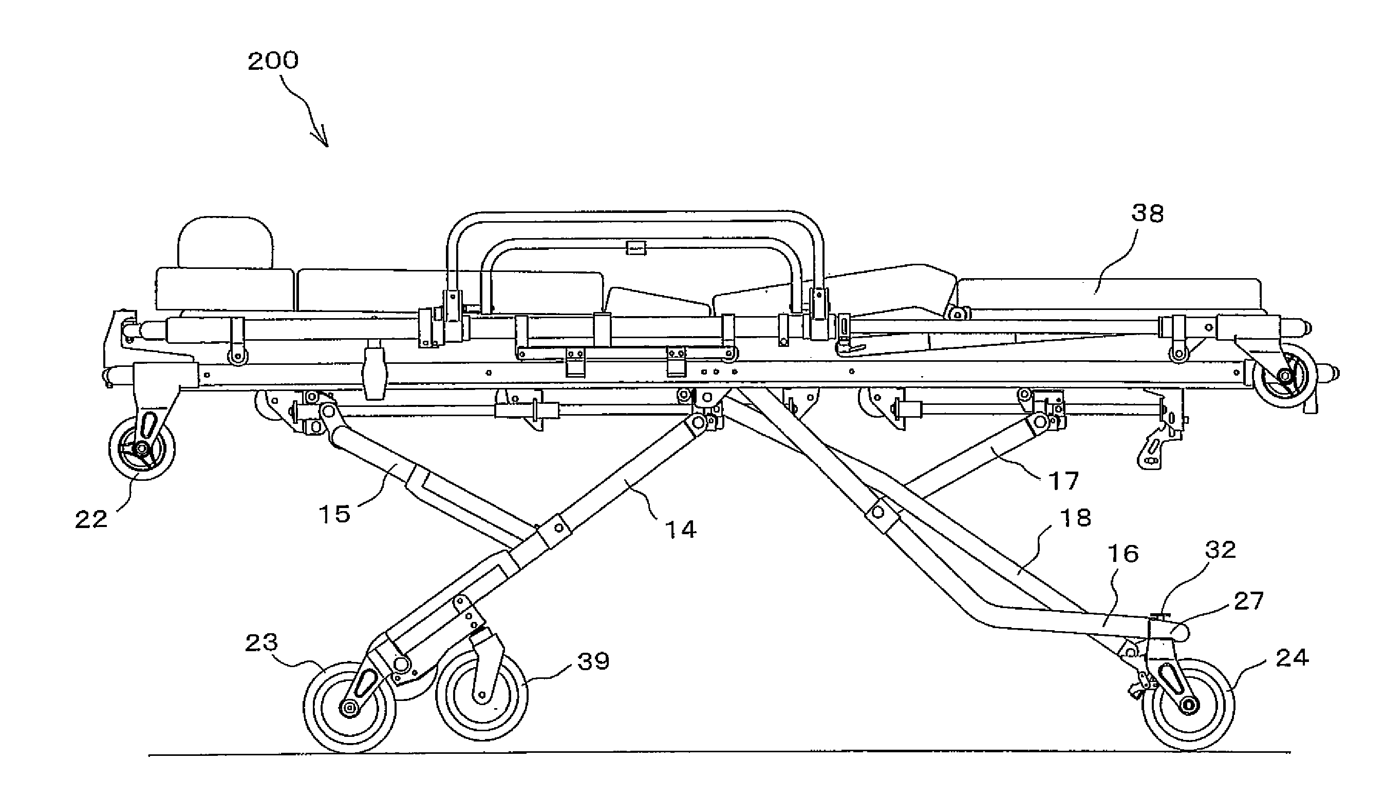
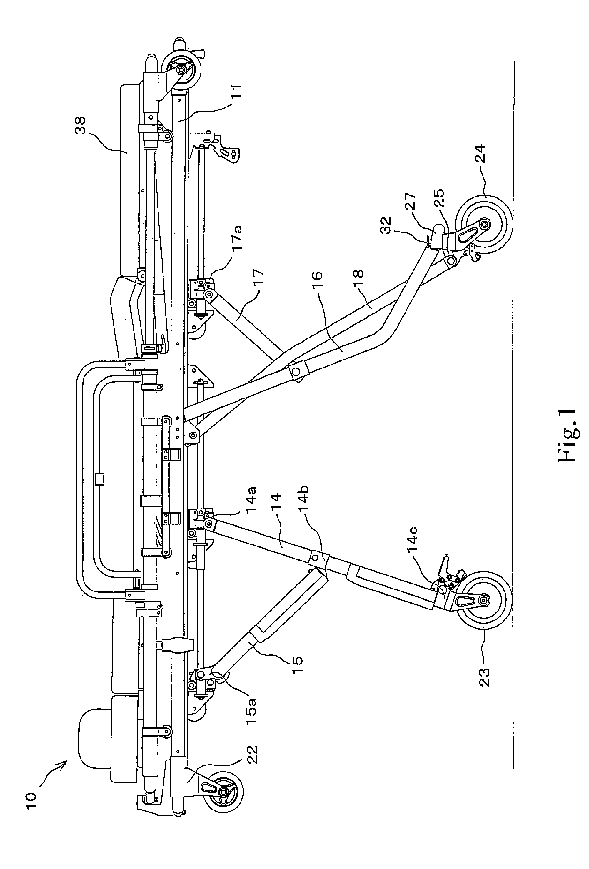
[0071]Six-wheeled stretchers 100, 200, 300, 400 according to the present invention is mounted in vehicles for transporting patient or the like and when a frame (upper frame) in which a lifter is mounted is used at a position lower than an intermediate position, rotatable auxiliary casters attached to front legs contact the ground and rotate with rotatable casters of rear legs, so that the stretcher can move forward and backward and left and right.

[0072]The six-wheeled stretchers 100, 200, 300, 400 according to the present invention each are a safe six-wheeled stretcher configured without forgetting to brake so that brakes are automatically applied on the rotatable casters of the rear legs when the stretcher is set to the lowest stage. Although described below in detail with reference to figures, the six-wheeled stretchers 100, 200, 300, 400 according to the present invention may be stretchers that have a lifter and can receive and transport the emergency patient, and to which rotata...


PUM


Abstract

According to the present invention, when a stretcher mounted in an ambulance car is used at an intermediate position with legs being folded, the stretcher can be moved forward and backward and left and right by rotatable casters. The stretcher (100) is provided with front leg fixed casters (23) fixed to front legs of the stretcher (100), and rotatable auxiliary casters (24) provided above the casters (23). When the stretcher (100) is set to the intermediate position, rotatable auxiliary casters (39) contact the ground in place of the front leg fixed casters (23), and together with the rotatable rear casters (24), make the stretcher (100) movable forward and backward and left and right.

Description

RELATED APPLICATIONS[0001]This application is a continuation of International Application PCT / JP2009 / 068450, having an international filing date of Oct. 28, 2009, now pending, which claims priority to Japanese Patent Application No. 2008-286352, having a filing date of Nov. 7, 2008, now pending, to Japanese Patent Application No. 2008-325099, having a filing date of Dec. 22, 2008, now pending, and to Japanese Patent Application No. 2009-142934, having a filing date of Jun. 16, 2009, now pending, and all of which are hereby incorporated herein by reference.TECHNICAL FIELD[0002]The present invention relates to a six-wheeled stretcher mounted in an ambulance car or the like. In particular, the present invention relates to a six-wheeled stretcher mounted in an ambulance car or the like, the stretcher being provided with rotatable auxiliary casters provided above casters fixed to front legs, and when located at a position lower than an intermediate stage, being supported by the rotatable...

Claims


Application Information

Patent Timeline
IPC IPC(8): A61G1/02
CPCA61G1/048A61G1/0562A61G2007/051A61G1/0237A61G1/0218A61G1/0212A61G1/0256A61G1/0287A61G1/0293A61G1/0262A61G7/051
Inventor GOTO, KAZUYUKIMATUNAGA, NORIYUKIMATUNAGA, SHIGEYUKI
Owner MATUNAGA MANUFACTORY
Why Eureka
Try Eureka