
Automatic Pixel Binning

a technology of pixel binning and automatic pixel binning, which is applied in the field of automatic pixel binning, can solve the problems that light sensors with small pixel sizes may have poor signal to noise response when used to capture scenes with low ambient ligh

Inactive Publication Date: 2011-11-03
HEWLETT PACKARD DEV CO LP
View PDF3 Cites 40 Cited by
  • Summary
  • Abstract
  • Description
  • Claims
  • Application Information

AI Technical Summary

Problems solved by technology

Light sensors with small pixel sizes may have poor signal to noise response when used capturing scenes with low ambient light.

Method used


Image

  • Automatic Pixel Binning
  • Automatic Pixel Binning
  • Automatic Pixel Binning

Examples


Embodiment Construction

The following discussion is directed to various embodiments of the invention. Although one or more of these embodiments may be preferred, the embodiments disclosed should not be interpreted, or otherwise used, as limiting the scope of the disclosure, including the claims. In addition, one skilled in the art will understand that the following description has broad application, and the discussion of any embodiment is meant only to be exemplary of that embodiment, and not intended to intimate that the scope of the disclosure, including the claims, is limited to that embodiment.

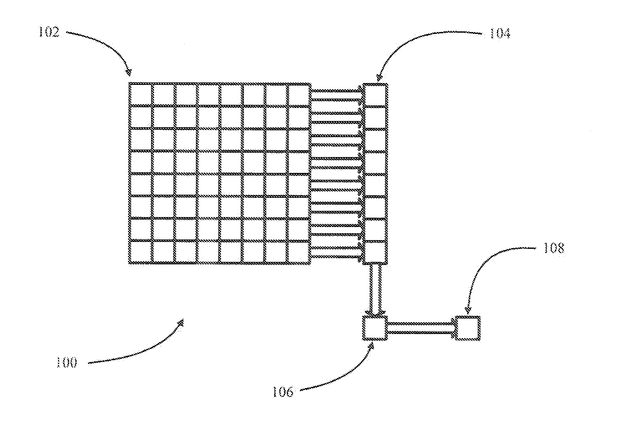
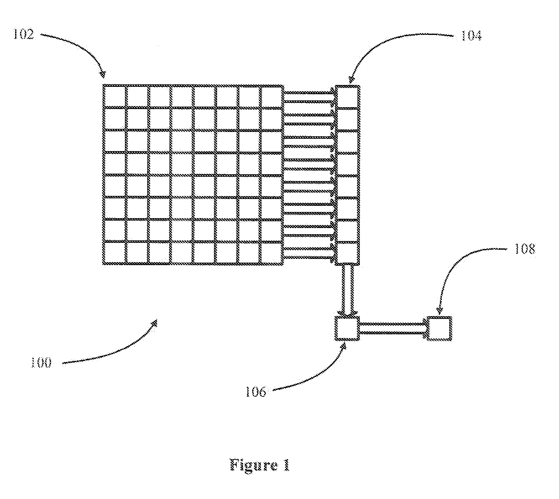
FIG. 1 is a block diagram of an imaging system 100 in an example embodiment of the invention. Imaging system 100 may be used in a video camera, for example a webcam or phone. Imaging system 100 comprises an image sensor 102, a shift register 104, an accumulator 106, and an analog to digital (ND) converter 108. Image sensor 100 comprises an array of light sensitive cells or pixels. The array of pixels is arranged ...


PUM


Abstract

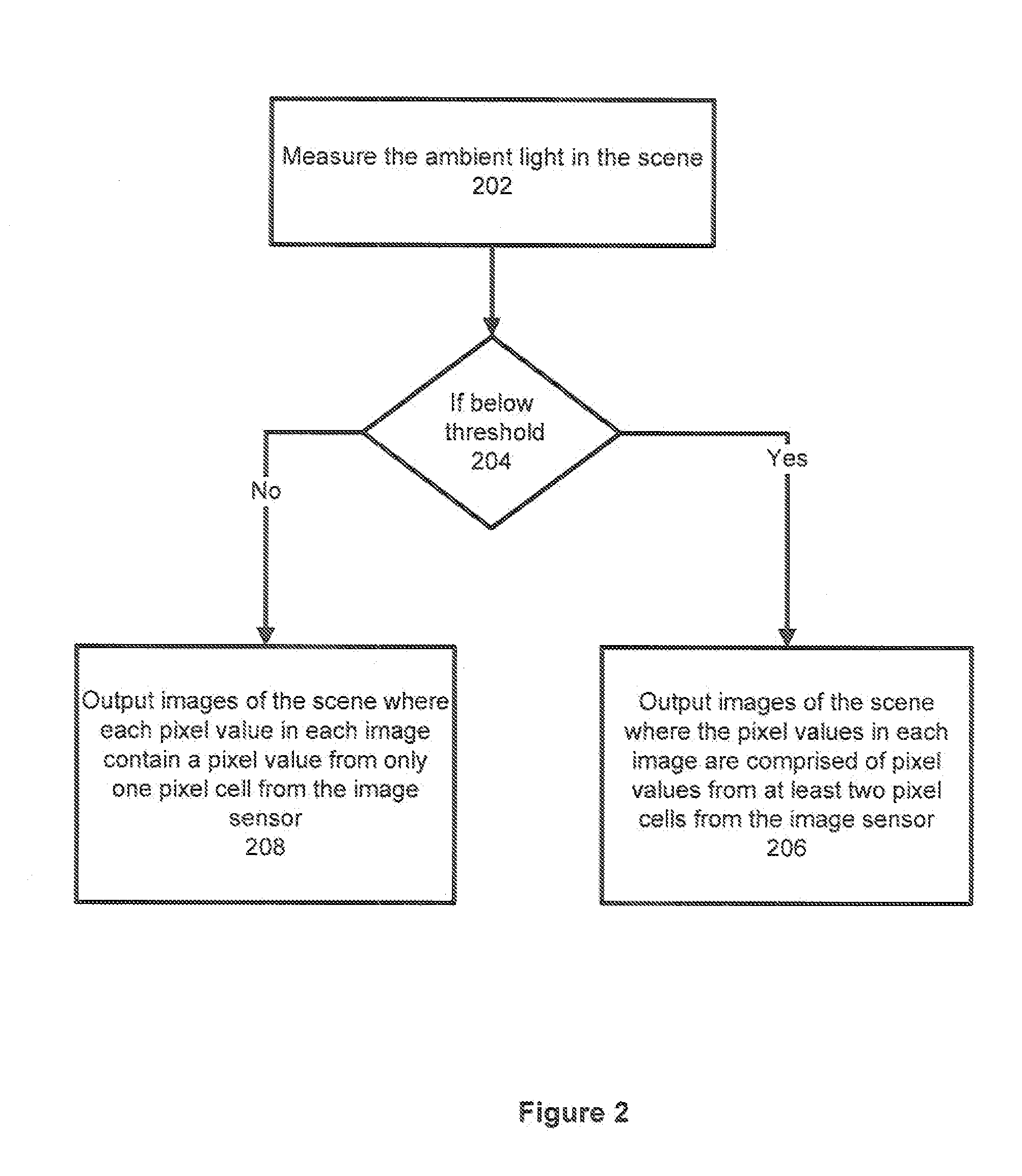
In accordance with at least some embodiments, a method for outputting video images is disclosed. The method starts by measuring the ambient light in a scene. When the ambient light in the scene is lower than a threshold, images of the scene are created in the analog domain by combining multiple pixel values from imaging cells in an image sensor. The analog image will have a lower resolution than the native resolution of the image sensor. The images of the scene are converted into the digital domain and up-sampled to match the native resolution of the image sensor. The up-sampled images are used as the outputted video images. When the ambient light in the scene is not lower than a threshold, images of the scene are outputted where each pixel value in the image is created from the pixel value from only one pixel cell in the image sensor.

Description

BACKGROUNDThe picture quality of video cameras, for example a webcam, is a function of the ambient light in the scene, the pixel size of the sensor, and the exposure or frame rate. As the resolution of video cameras increase, the pixel size in the sensor continues to decrease. Light sensitivity of the sensors is a function of the pixel size. Light sensors with small pixel sizes may have poor signal to noise response when used capturing scenes with low ambient light.BRIEF DESCRIPTION OF THE DRAWINGSFor a detailed description of exemplary embodiments of the invention, reference will now be made to the accompanying drawings in which:FIG. 1 is a block diagram of an imaging system 100 in an example embodiment of the invention.FIG. 2 is a flow chart 200 in an example embodiment of the invention.NOTATION AND NOMENCLATURECertain terms are used throughout the following description and claims to refer to particular system components. As one skilled in the art will appreciate, computer compani...

Claims


Application Information

Patent Timeline
IPC IPC(8): H04N5/235
CPCH04N5/23245H04N5/378H04N5/347H04N23/667H04N25/46H04N25/75
Inventor ATKINSON, LEE WARREN
Owner HEWLETT PACKARD DEV CO LP
Learn More