Controller for a Resonant Switched-Mode Power Converter

Active Publication Date: 2011-11-03
INFINEON TECH AG
View PDF9 Cites 35 Cited by
  • Summary
  • Abstract
  • Description
  • Claims
  • Application Information

AI Technical Summary

Problems solved by technology

A design issue for resonant power converters is the need to provide suitable timing for the control signal that controls a synchronous rectifier on the secondary side of the power train relative to the timing of a control signal that controls a primary-side power switch therein.

Method used


Image

  • Controller for a Resonant Switched-Mode Power Converter
  • Controller for a Resonant Switched-Mode Power Converter
  • Controller for a Resonant Switched-Mode Power Converter

Examples


Embodiment Construction

[0031]The making and using of the presently preferred embodiments are discussed in detail below. It should be appreciated, however, that the present invention provides many applicable inventive concepts that can be embodied in a wide variety of specific contexts. The specific embodiments discussed are merely illustrative of specific ways to make and use the invention, and do not limit the scope of the invention.

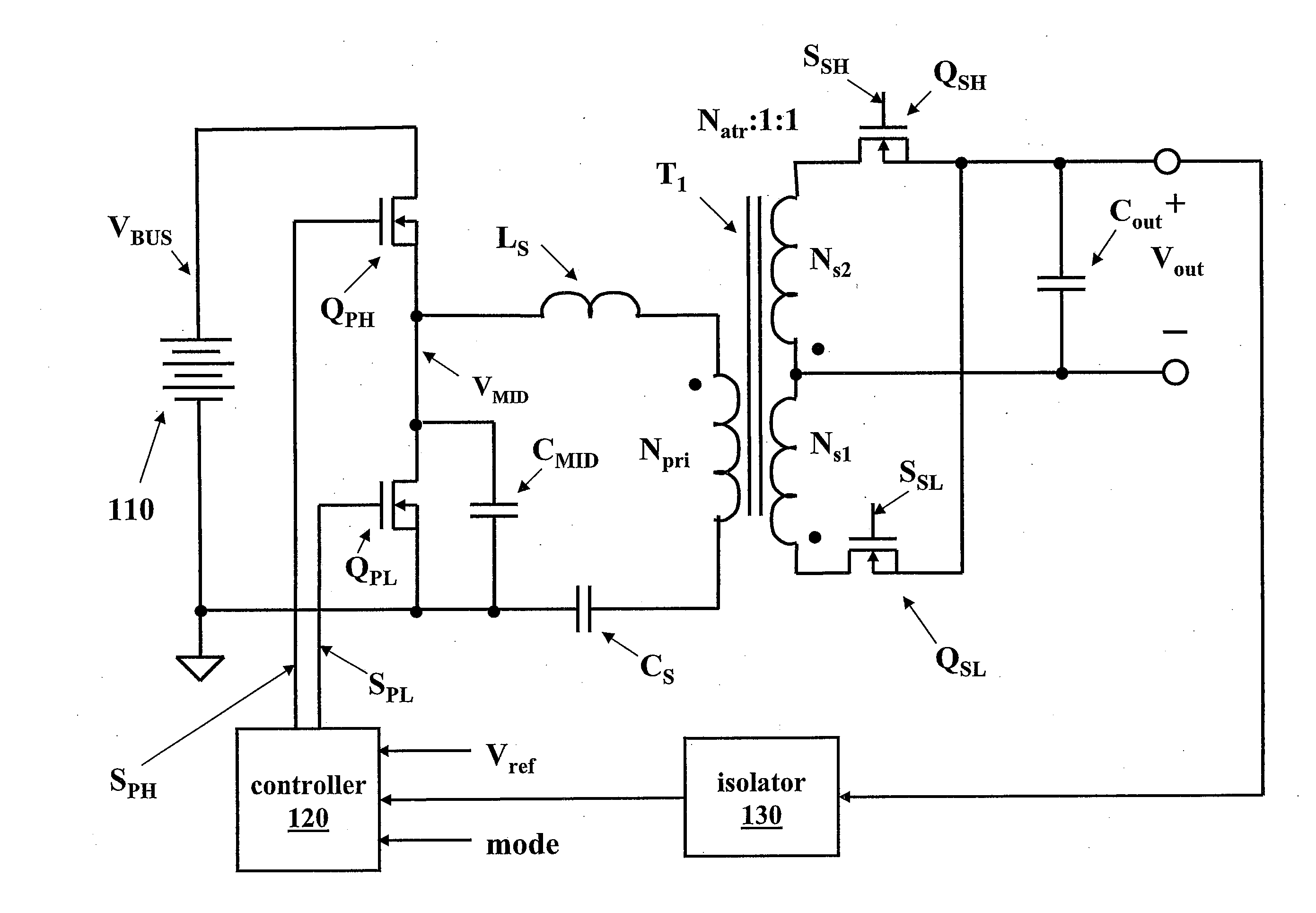
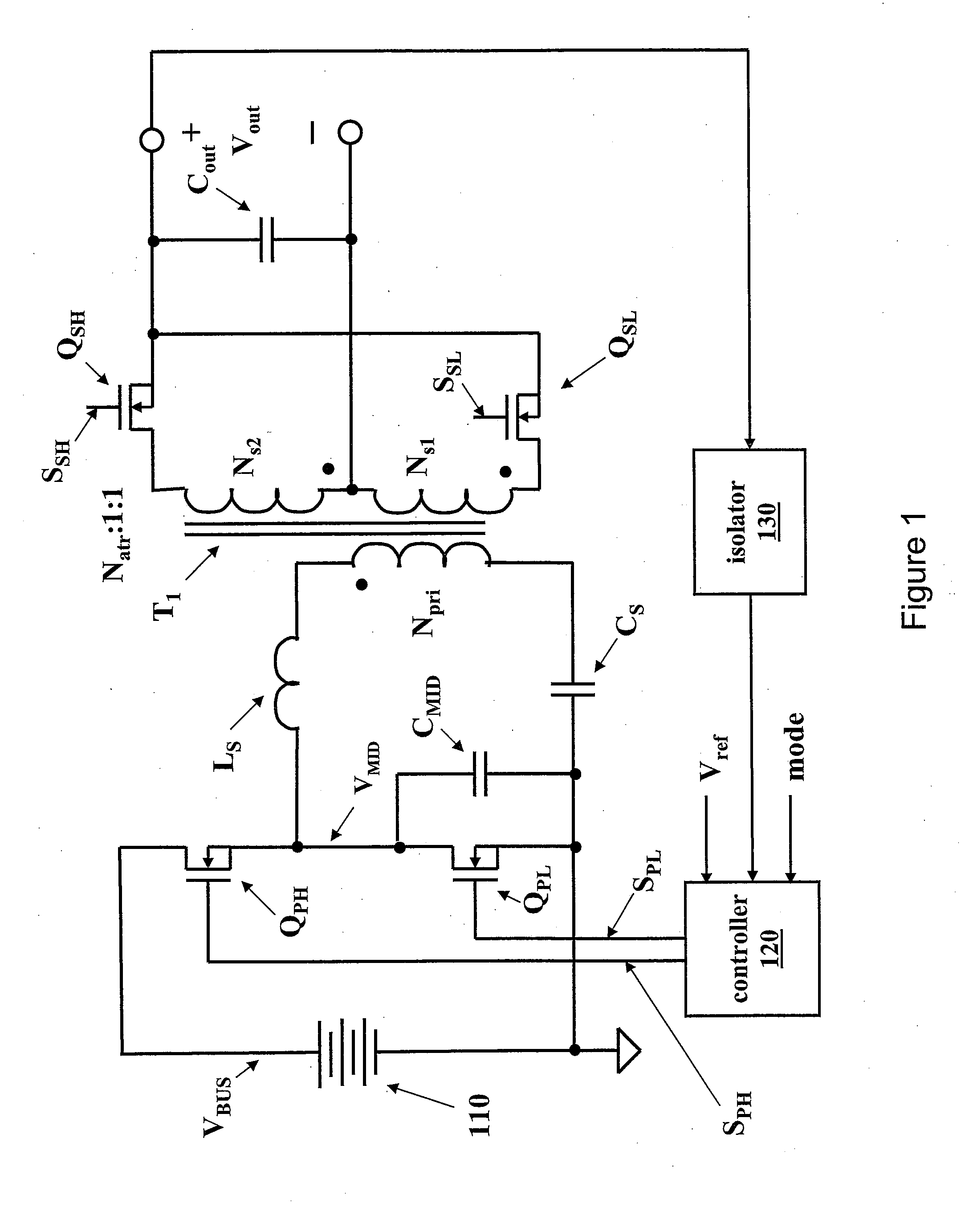
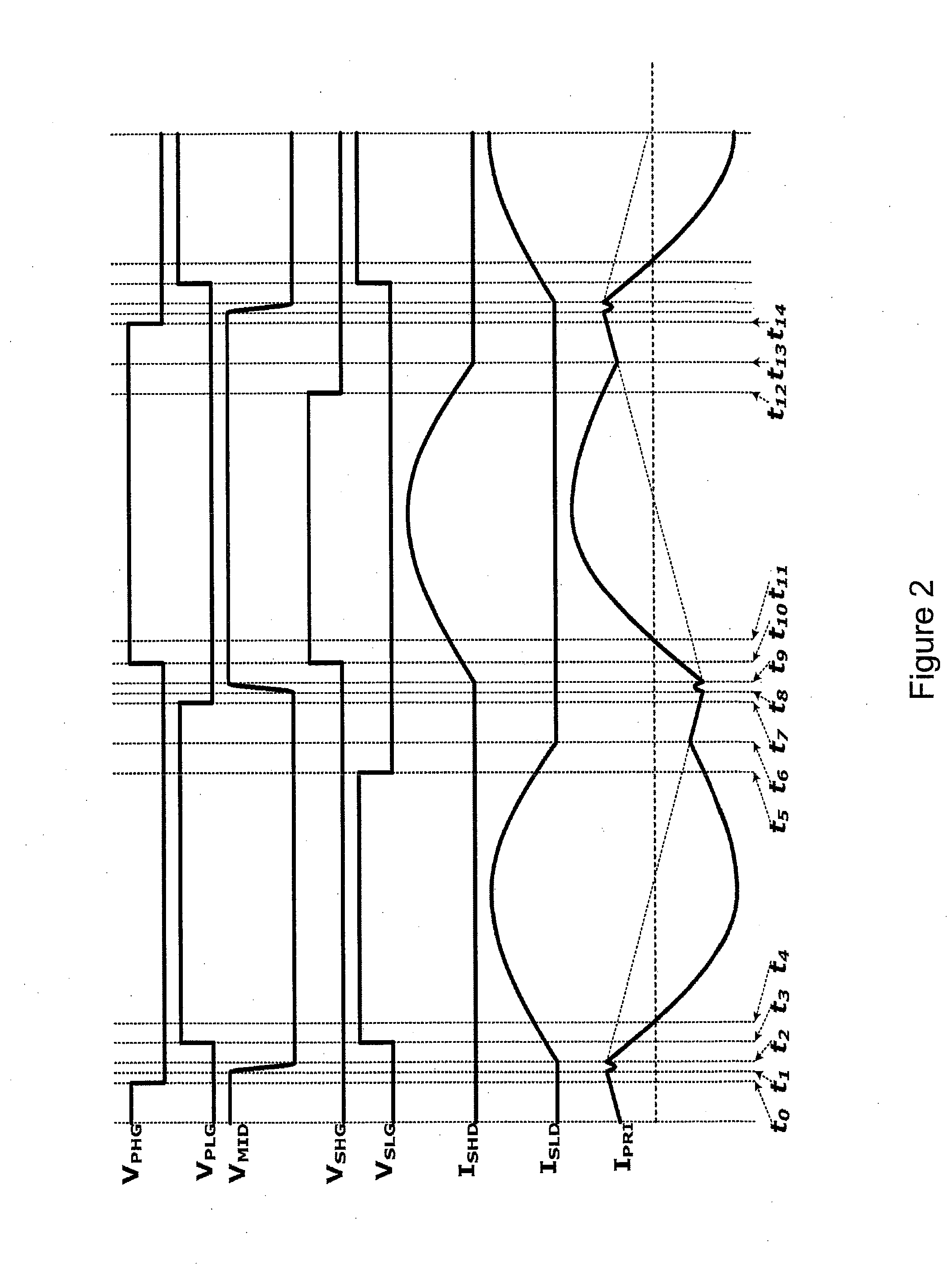
[0032]The present invention will be described with respect to exemplary embodiments in a specific context, namely a resonant switched-mode power converter formed with a controller configured to provide a control signal for a secondary-side synchronous rectifier with suitable delay with respect to timing of a primary-side power switch.

[0033]An embodiment of the invention may be applied to various electronic power conversion devices, for example, to a half-bridge resonant power converter constructed with a controller configured to produce a control signal for secondary-side syn...


PUM


Abstract

An embodiment of the invention relates to an LLC power converter including a controller configured to regulate an output characteristic of the power converter by controlling a power converter switching frequency. In a first mode of operation, the controller turns off a secondary-side power switch earlier than a turn-off time of a primary-side power switch by a time difference that is controlled by a resistor coupled to an external circuit node. In a second mode of operation, the controller turns on a secondary-side power switch at substantially the same time as the primary-side power switch, and turns off the secondary-side power switch after a maximum on time that is a nonlinear function of a load current of the power converter. The nonlinear function is a substantially constant function of the load current for a value of the load current higher than a threshold value.

Description

TECHNICAL FIELD[0001]An embodiment of the invention relates generally to electronic power conversion and methods, and more particularly to the use of a controller for a primary-side and a secondary-side power switch in a resonant switched-mode power converter.BACKGROUND[0002]A switched-mode power converter (also referred to as a “power converter” or “regulator”) is a power supply or power processing circuit that converts an input voltage waveform into a specified output voltage waveform. DC-DC power converters convert a dc input voltage which may be time varying into a dc output voltage. Controllers associated with the power converters manage an operation thereof by controlling conduction periods or switching frequencies of switches employed therein. Generally, the controllers are coupled between an input and output of the power converter in a feedback loop configuration (also referred to as a “control loop” or “closed control loop”).[0003]Typically, the controller measures an outpu...

Claims


Application Information

Patent Timeline
Patent Type & Authority Applications(United States)
IPC IPC(8): H02M3/335
CPCH02M3/33592H02M3/3378Y02B70/1491Y02B70/1475H02M2001/0058Y02B70/1433Y02B70/10H02M1/0058
Inventor HE, YICHAN, TUCK MENGTEO, YONG SIANGGONG, XIAOWUJEOH, MENG KIAT
Owner INFINEON TECH AG
Why Eureka
Try Eureka