Protective socket for use with a parallel optical transceiver module for protecting components of the module from airborne matter

a technology of protecting sockets and modules, applied in the field of optical communication systems, can solve problems such as performance problems, problems in modules, and challenges in designing and implementing a suitable heat dissipation system

Inactive Publication Date: 2011-11-03
BROADCOM INT PTE LTD
View PDF12 Cites 27 Cited by
  • Summary
  • Abstract
  • Description
  • Claims
  • Application Information

AI Technical Summary

Benefits of technology

[0009]In accordance with another embodiment, an external heat sink device and method are provided for protecting an optical transceiver module from airborne matter. The external heat sink device has a protective cover formed therein. The protective cover has first, second, third, and fourth side walls and a bottom. The bottom corresponds to a surface of the external heat sink device. The first, second, third and fourth side walls and the bottom define a receptacle having a length, a width and a height. When the external heat sink device is placed in contact with the optical transceiver module, the receptacle surrounds the optical transceiver module such that the side walls and bottom of the protective cover prevent or limit ingress of airborne particulates into an interior portion of the optical transceiver module.
[0010]The method, in accordance with this latter embodiment, comprises providing an external heat sink device having a protective cover formed therein, and placing the external heat sink device in contact with the optical transceiver module such that a receptacle of the protective cover defined by the first, second, third, and fourth side walls and the bottom surrounds the optical transceiver module to prevent or limit ingress of airborne particulates into an interior portion of the optical transceiver module.

Problems solved by technology

Due to the large amounts of heat generated, the tasks associated with designing and implementing a suitable heat dissipation system are challenging.
Ingress of such airborne matter into the module can sometimes cause problems in the modules.
For example, ingress of dust into a part of the module that contains the laser diodes can potentially block light output from the laser diodes or received by the photodiodes, which, in turn, can lead to performance issues.
Therefore, while an open module design provides certain benefits, such designs are susceptible to problems associated with the ingress of dust, dirt, gases and other airborne matter.
These gases can find their way into a module and erode metal components of the module (e.g., bond wires, conductors, etc.), thereby causing damage to the module that can lead to performance problems.

Method used


Image

  • Protective socket for use with a parallel optical transceiver module for protecting components of the module from airborne matter
  • Protective socket for use with a parallel optical transceiver module for protecting components of the module from airborne matter
  • Protective socket for use with a parallel optical transceiver module for protecting components of the module from airborne matter

Examples


Embodiment Construction

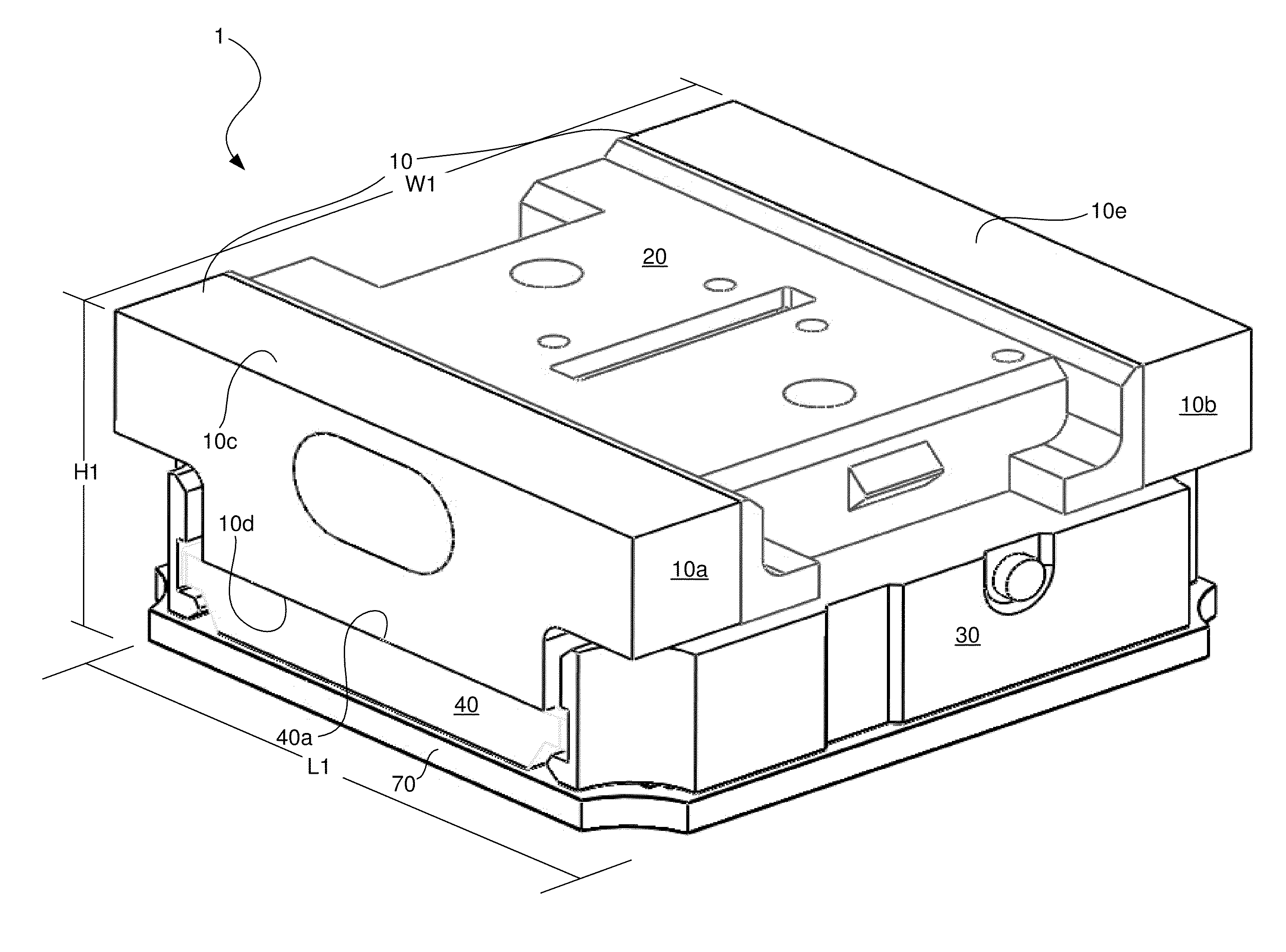
[0025]In accordance with the invention, a protective socket for use with a parallel optical transceiver module is provided. When the parallel optical transceiver module is seated within a receptacle of the protective socket, the side walls and bottom of the protective socket that define the receptacle protect the internal components of the parallel optical transceiver module from dirt, dust, gases, and other particulates. Prior to describing an illustrative embodiment of the protective socket, an illustrative embodiment of a parallel optical transceiver module with which the protective socket may be used will be described with reference to FIGS. 1-3. An illustrative embodiment of the protective socket and other features will then be described with reference to FIGS. 4-13.

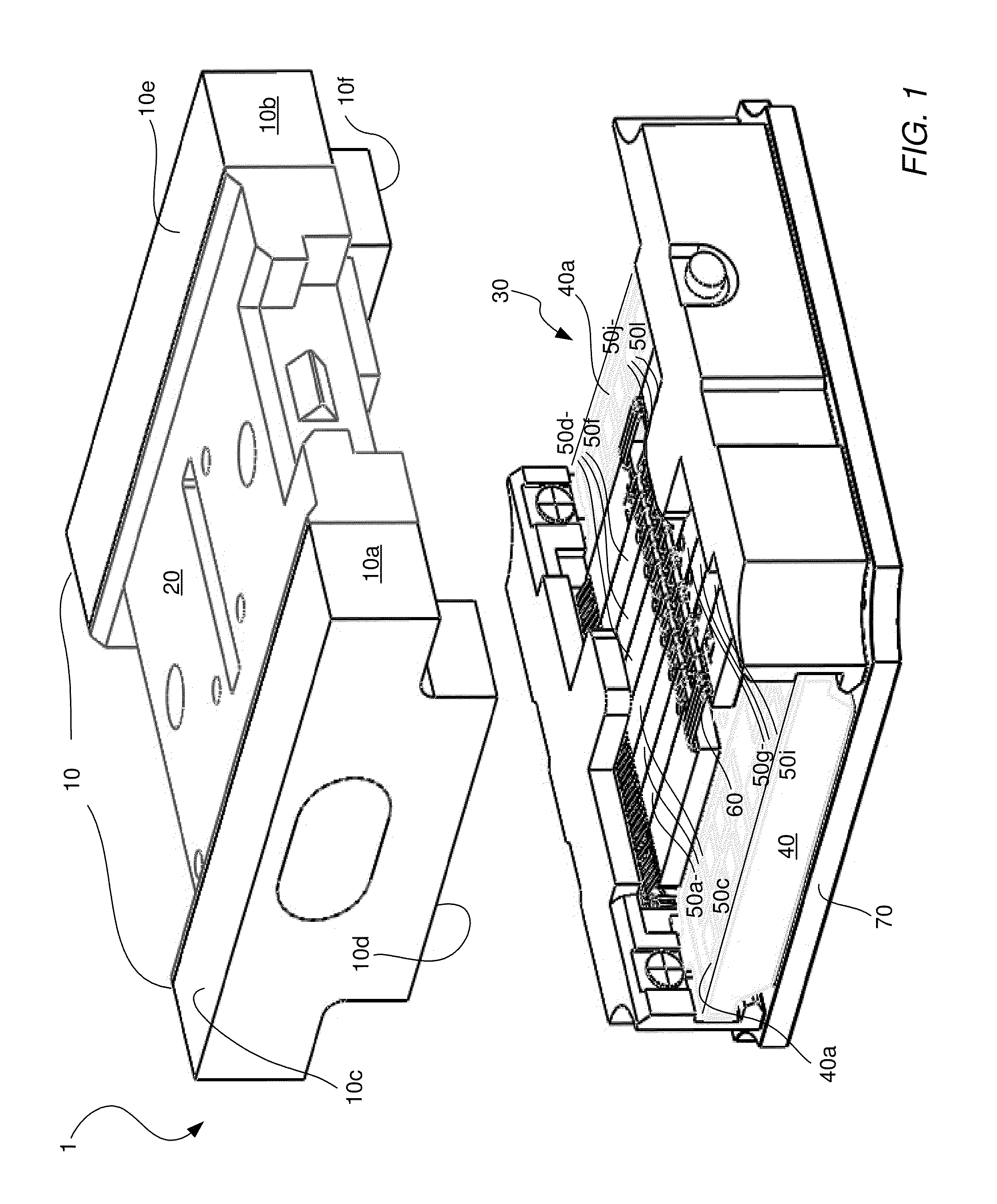
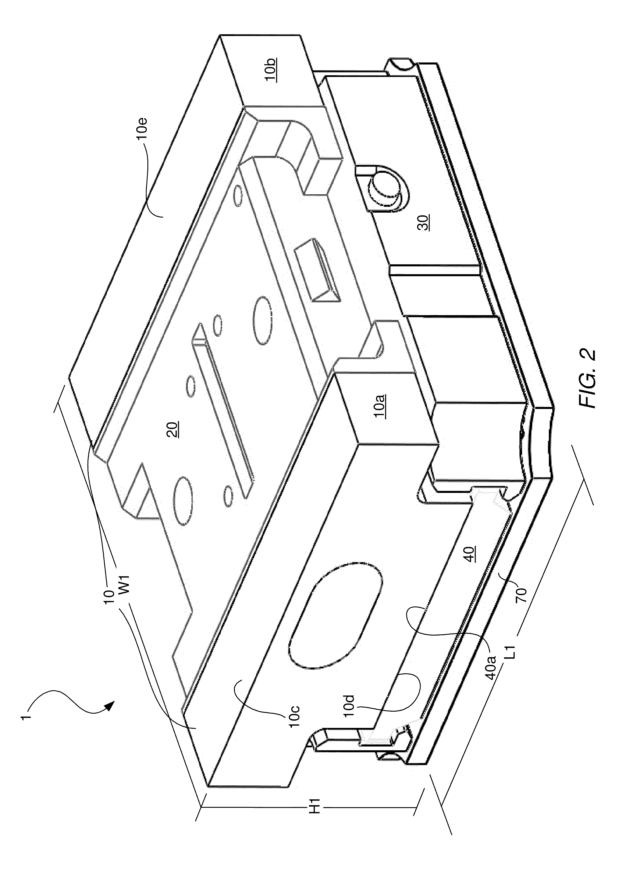
[0026]FIG. 1 illustrates a perspective view of a parallel optical transceiver module 1 in accordance with an illustrative embodiment. The parallel optical transceiver module 1 includes a heat dissipation system 10, ...


PUM


Abstract

A protective socket is provided for use with a parallel optical transceiver module. When the parallel optical transceiver module is seated within a receptacle of the protective socket, the side walls and bottom that define the receptacle of the protective socket protect the internal components of the parallel optical transceiver module from dirt, dust, gases, and other airborne matter.

Description

TECHNICAL FIELD OF THE INVENTION[0001]The invention relates to optical communications systems. More particularly, the invention relates to a protective socket for use with a parallel optical transceiver module that protects components of the module from airborne matter, such as dirt, dust, and gases.BACKGROUND OF THE INVENTION[0002]Parallel optical transceiver modules typically include a plurality of laser diodes for generating optical data signals, laser diode driver circuitry for driving the laser diodes, a controller for controlling operations of the transceiver module, receiver photodiodes for receiving optical data signals, receiver circuitry for demodulating and decoding the received optical data signals, and monitor photodiodes for monitoring the output power levels of the laser diodes. Parallel optical transceiver modules typically also include an optical subassembly having optical elements that direct the optical data signals produced by the laser diodes onto the ends of op...

Claims


Application Information

Patent Timeline
Patent Type & Authority Applications(United States)
IPC IPC(8): G02B6/36G02B6/00
CPCG02B6/4214G02B6/4246G02B6/4249G02B6/4292G02B6/4261G02B6/4284G02B6/4251
Inventor MEADOWCROFT, DAVID J.K.CHAN, SENG-KUM
Owner BROADCOM INT PTE LTD
Why Eureka
Try Eureka