Method for obtaining ceramic coatings and ceramic coatings obtained

Inactive Publication Date: 2011-11-03
FUNDACION INASMET
View PDF1 Cites 23 Cited by
  • Summary
  • Abstract
  • Description
  • Claims
  • Application Information

AI Technical Summary

Benefits of technology

[0002]The process of the invention allows generating very dense ceramic layers with

Problems solved by technology

Although controlled atmosphere plasma spray (VPS and LPPS) involves certain benefits in relation to the minimum thicknesses achieved and the density of the coating, these processes have the drawback of their high price and low production, as well as the dimensional limitations for the pieces to be treated derived from the need to use vacuum chambers.
However, the gas flow rates generated by plasma systems are generally moderate (100-200 m/s), producing coatings with insufficient densities and/or adherences for many industrial applications.
However, all these alternatives imply prolonging the production chain and therefore increasing process costs.
Furthermore, the high melting point and low conductivity of refractory ceramics limit the processing of these materials by means of conventional continuous combustion techniques.
However, there is growing interest in the use of techniques of high velocity continuous combustion such as high velocity oxy-fuel (HVOF) and pulse detonation (D-Gun) to improve the quality, compaction and hardness of the ceramic coating, though there are very few successful references of this approach.
The limitation of these techniques is focused on the short residence time of the particles of the coating material in the flame (combustion stream), and accordingly, the deficient heating thereof.
The acceleration of particles of the unmelted coating material in the flame results in a grit blasting effect on the previously deposited material, preventing an efficient formation of the coating layer.
In conventional plasma spray processes, the difference between the coefficient of thermal expansion of the substrate and the coating may cause considerable residual stress in the co

Method used


Image

  • Method for obtaining ceramic coatings and ceramic coatings obtained
  • Method for obtaining ceramic coatings and ceramic coatings obtained
  • Method for obtaining ceramic coatings and ceramic coatings obtained

Examples


Example

Example 1

[0069]The following was used as a coating material: angular particles (−22.5+5 μm) of ZrO2 partially stabilized with 7% by weight of Y2O3 (Amperit 825.0). The spray was performed by means of high frequency pulse detonation techniques with the following parameters:[0070]Propylene flow rate (slpm): 50[0071]Oxygen flow rate (slpm): 180[0072]Frequency (Hz): 60[0073]Nitrogen carrier gas (slpm): 50[0074]Feed: 18 g / min, a coating of approximately 40 μm thick being obtained in a single pass at a relative speed of 5 cm / s.[0075]Spray distance (mm): 40

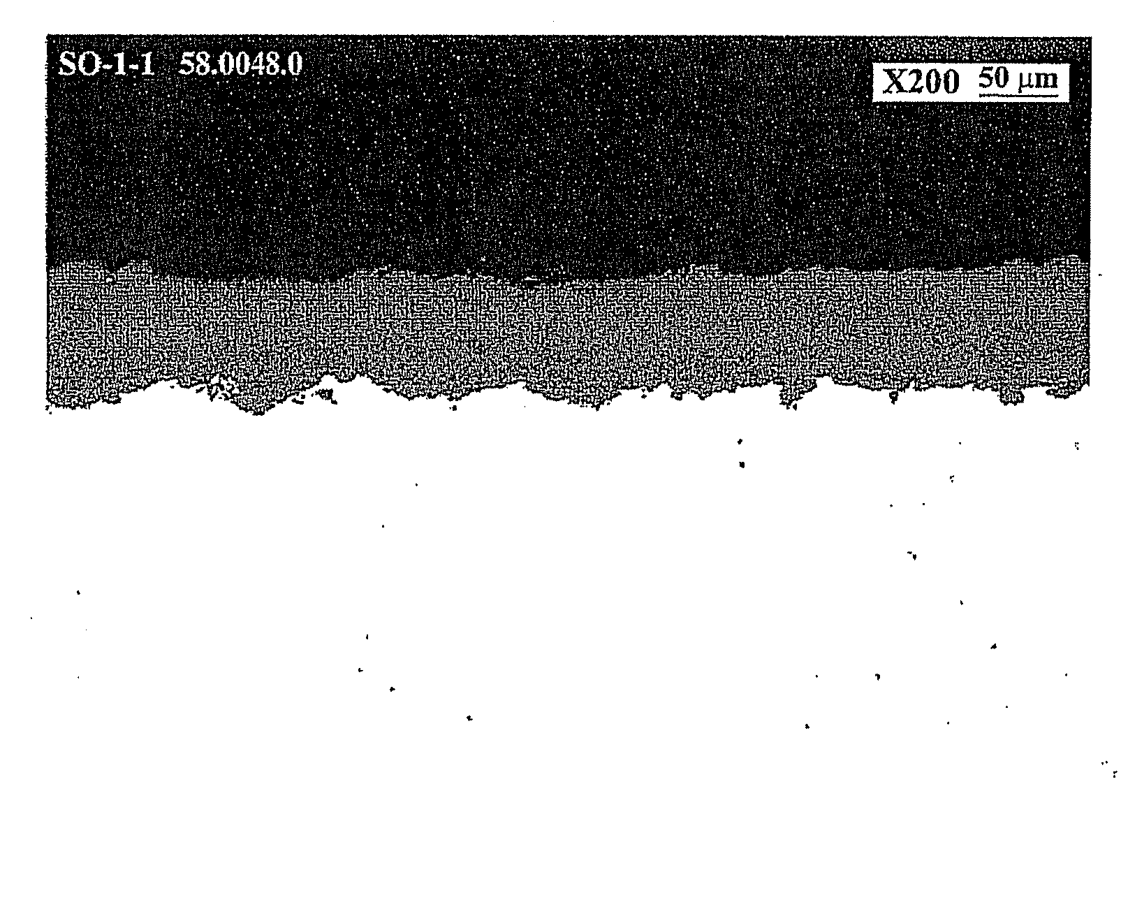
[0076]A coating with a hardness of 934 HV0.3 and a porosity less than 1% was obtained with these parameters. The microstructure of this coating can be observed in FIG. 6.

Example

Example 2

[0077]The following was used as a coating material: angular particles (−25 μm) of ZrO2 completely stabilized with 8% mol Y2O3 (of Treibacher). The spray was performed by means of high frequency pulse detonation techniques with the following parameters:[0078]Propylene flow rate (slpm): 50[0079]Oxygen flow rate (slpm): 180[0080]Frequency (Hz): 60[0081]Nitrogen carrier gas (slpm): 50[0082]Feed: 36 g / min, a coating of approximately 130 μm thick being obtained in a single pass at a relative speed of 5 cm / s.[0083]Spray distance (mm): 40[0084]Preheating of the substrate a 200 ° C.

[0085]A coating was obtained with these parameters with an average hardness of 944 HV0.3 and a porosity less than 1%, the microstructure of which is observed in FIG. 7.

Example

Example 3

[0086]The following was used as a coating material: angular particles (−22+5 μm) of Al2O3. The spray was performed by means of high frequency pulse detonation techniques with the following parameters:[0087]Propylene flow rate (slpm): 50[0088]Oxygen flow rate (slpm): 180[0089]Frequency (Hz): 50[0090]Nitrogen carrier gas (slpm): 40[0091]Feed (g / min): 28[0092]Spray distance (mm):[0093]a: 40 mm, a coating of approximately 300 μm thick being obtained in a single pass at a relative speed of 5 cm / s.[0094]b: 150 mm, a coating of approximately 200 μm thick being obtained in a single pass at a relative speed of 5 cm / s.

[0095]Coatings with porosity less than 2% and with an average hardness of: a) 1116 HV0.3, the microstructure of which is observed in FIG. 8, and b) 996 HV0.3, were obtained with these parameters. As can be observed, the deposition distance can significantly affect the degree of compaction of the layer, as a result of the loss of energy of the particles.


PUM

PropertyMeasurementUnit
Fractionaaaaaaaaaa
Fractionaaaaaaaaaa
Timeaaaaaaaaaa

Abstract

The invention relates to a process for obtaining ceramic coatings and ceramic coatings obtained. This process allows obtaining coatings of ceramic oxides, such as ZrO2, Al2O3, TiO2, Cr2O3, Y2O3, SiO2, CaO, MgO, CeO2, Sc2O3, MnO, and/or complex mixtures thereof, by means of a high frequency pulse detonation technique in which the relative movement between the combustion stream and the substrate or piece to be coated takes place at a speed that produces an overlap between the successive coating areas exceeding 60% of the surface of a coating area. The allows producing ceramic coatings with a thickness greater than 30 microns in a single pass.

Description

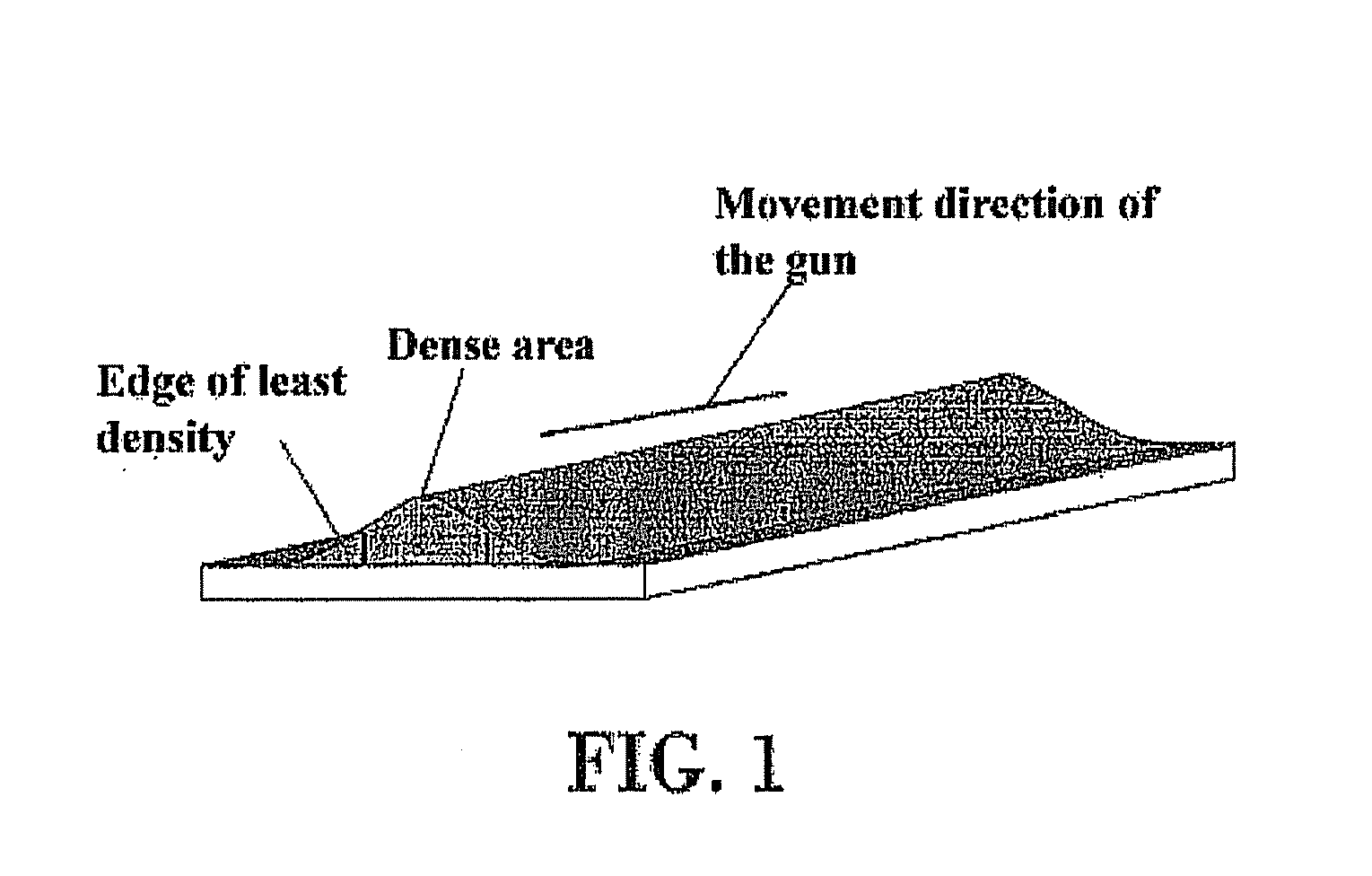
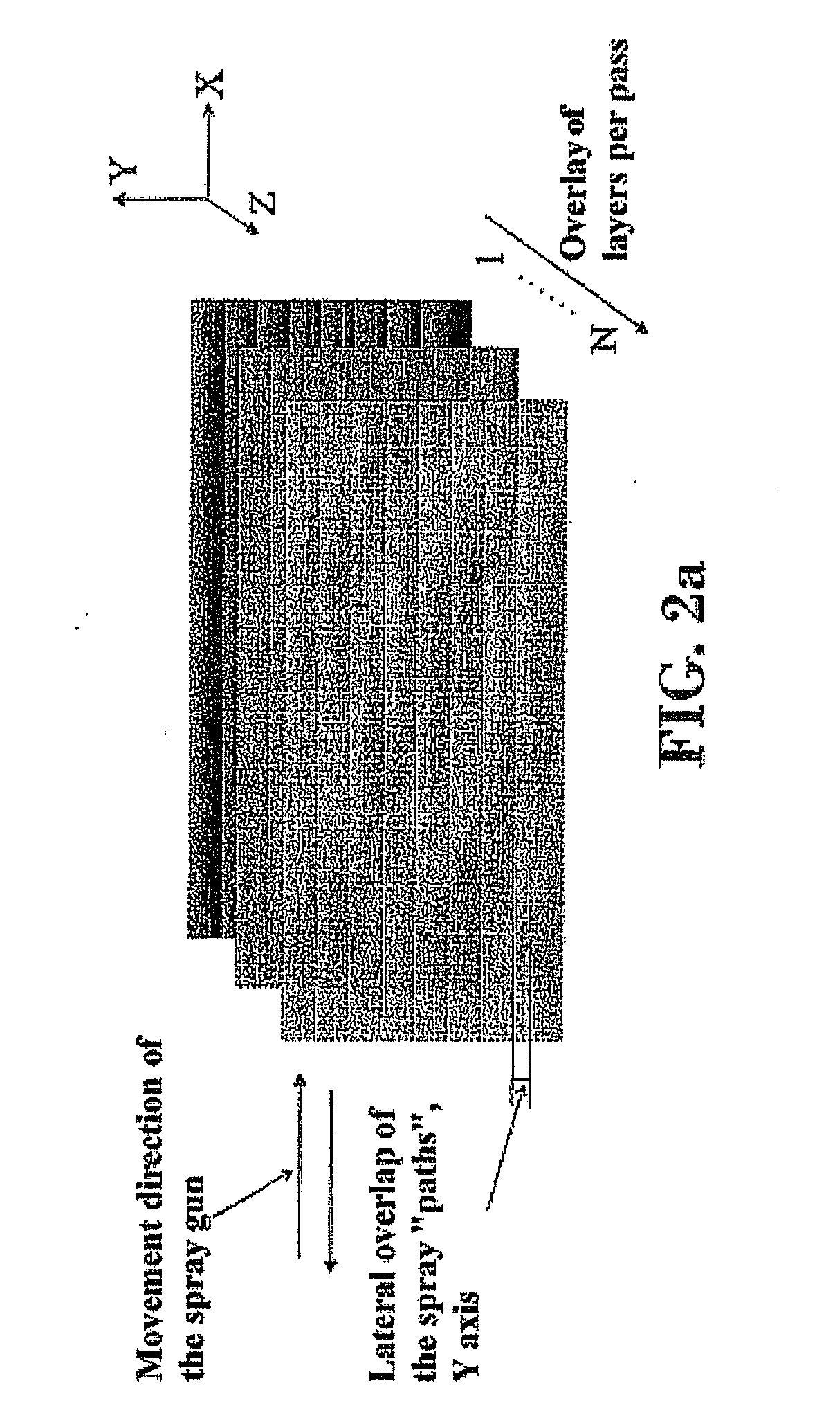
OBJECT OF THE INVENTION[0001]The present invention is comprised within the field of processes for obtaining ceramic coatings and more specifically, processes using high frequency pulse detonation thermal spray techniques.[0002]The process of the invention allows generating very dense ceramic layers with moderate heating of the substrate determined by the low consumption of process gases.[0003]The process of the invention is especially suitable for obtaining ceramic coatings such as ZrO2, Al2O3, TiO2, Cr2O3, Y2O3, SiO2, CaO, MgO, CeO2, Sc2O3, MnO, and / or mixtures thereof.BACKGROUND OF THE INVENTION[0004]Techniques for obtaining coatings by thermal spray are based on generating a combustion flame or stream to process a coating material which, by means of equipment generically known as guns, is directed or sprayed towards the substrate or piece to be coated, producing coating points or areas in one part of the surface of the substrate to be coated. The coating material is fed into the ...

Claims


Application Information

Patent Timeline
IPC IPC(8): C23C4/10B32B3/26C01G25/02C01F7/02C01F11/02C01G37/02C01F17/00C01B33/12C01F5/00C01G45/02B32B9/00C01G23/047
CPCC23C4/105Y10T428/26C23C4/122C23C4/11C23C4/126Y10T428/249953
Inventor FAGOAGA ALTUNA, INAKIPARCO CAMACARO, MARIABARIKYN, GEORGIYVAQUERO GONZALEZ, CARLOS
Owner FUNDACION INASMET
Why Eureka
Try Eureka