Threading insert with cooling channels

a technology of cooling channels and thread inserts, which is applied in the direction of turning equipment, boring/drilling equipment, drilling tools, etc., can solve the problems of poor conductors of hardening coatings, inability to improve the cooling and flow of chips from conventional cutting inserts carried out to achieve the effect of improving the cooling and flow of chips

Inactive Publication Date: 2005-10-25
SIDERCA S A L C ARGENTINA
View PDF23 Cites 63 Cited by
  • Summary
  • Abstract
  • Description
  • Claims
  • Application Information

AI Technical Summary

Problems solved by technology

Notwithstanding the chip breaking effect of high pressure liquid, when a cutting insert, during an operation such as turning, cuts loose a chip from a rotating workpiece, usually of metal, considerable amounts of heat are generated.
However, the attempts to improve the cooling and the flow of the chip away from conventional cutting insert carried out hitherto have not been entirely successful because of the coatings used on cutting inserts and the placement of the cooling channels.
We have recognized, however, that the hardening coatings are poor conductors.
Moreover, the cooling channels are sometimes obstructed by the chip flow and therefore heat removal decreases.
In addition, in conventional threading inserts, the cooling channels are coated with tungsten carbide, which reduces the effectiveness of the cooling liquid.

Method used


Image

  • Threading insert with cooling channels
  • Threading insert with cooling channels
  • Threading insert with cooling channels

Examples


Embodiment Construction

[0019]The present invention includes a threading insert modified with cooling channels in an innovative way for extending tool life.

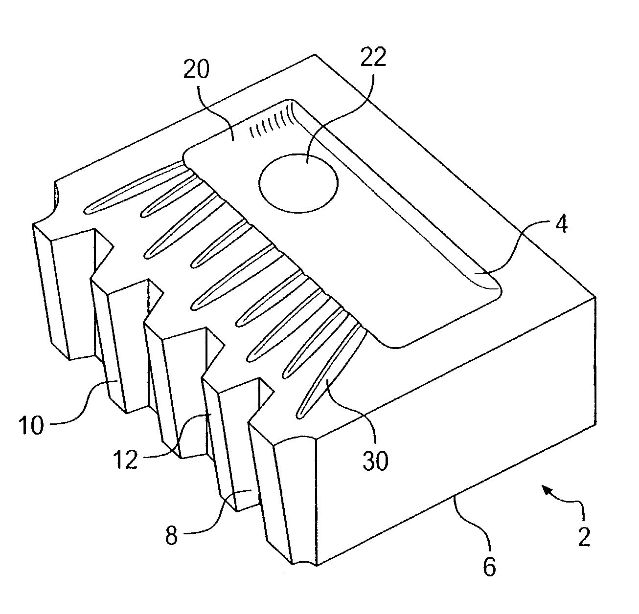
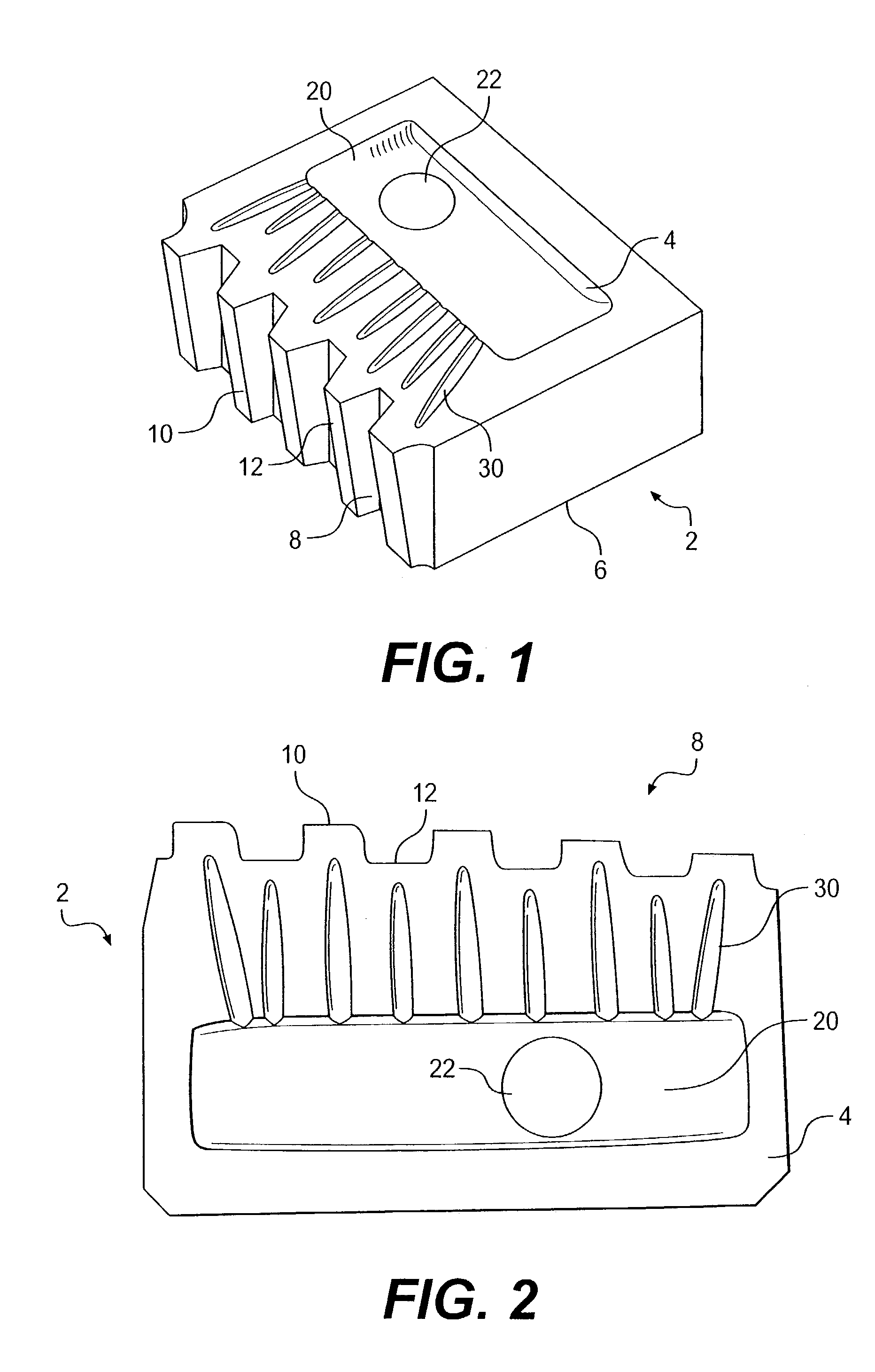
[0020]FIG. 1 shows a threading insert 2, which generally comprises a top side 4, a bottom side 6 and a front side 8. The front side 8 includes a plurality of crests 10 and valleys 12 which are the cutting surfaces that form threads in a workpiece.

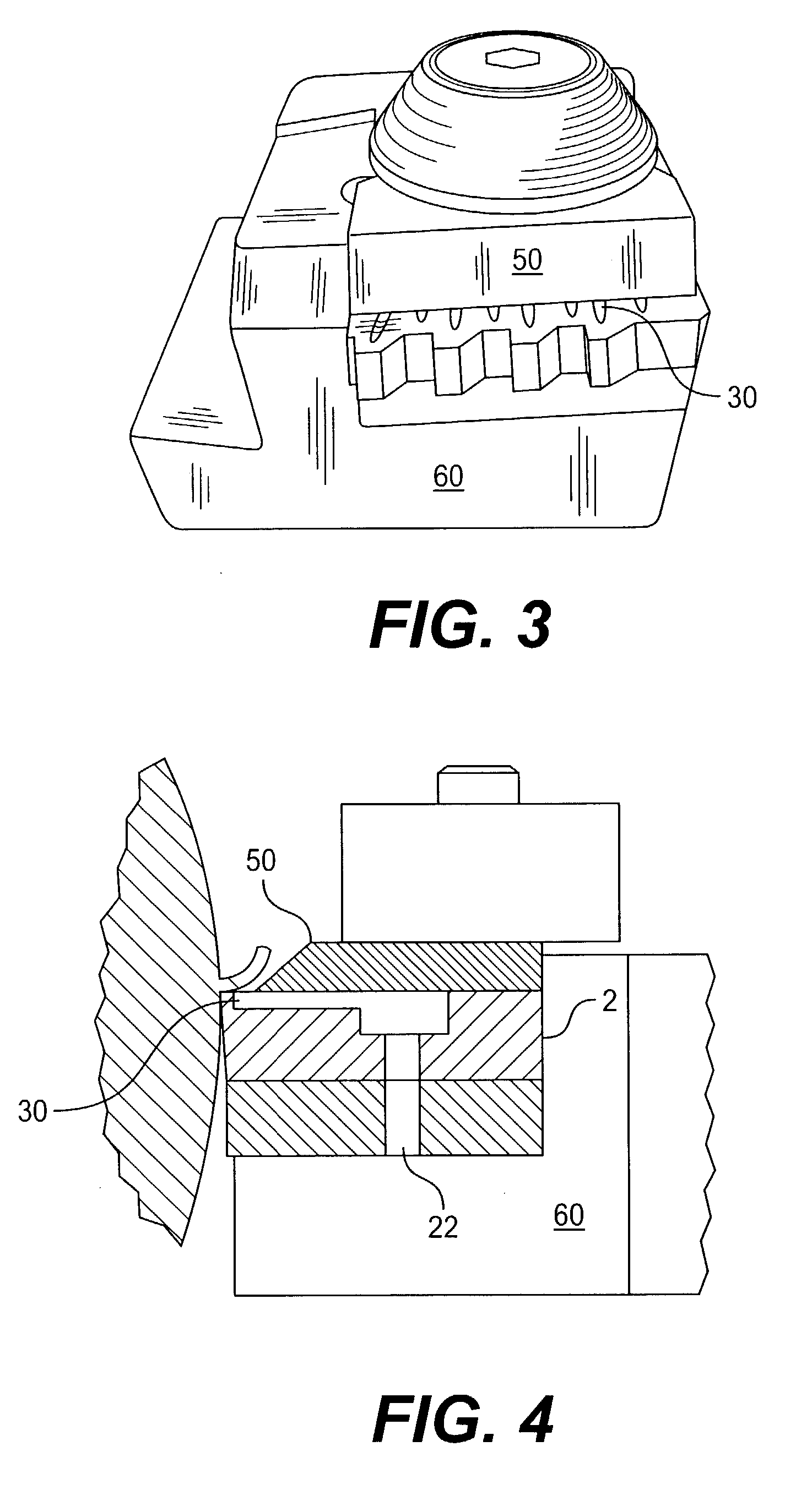
[0021]As shown in FIG. 2, the top side 4 of the cutting insert 2 has a reservoir tray 20 formed therein. Within the reservoir tray 20 is a hole 22 that extends through the cutting insert 2, and is adapted to align with a conduit carrying pressurized coolant from a lathe or other metalworking machine. The top side 4 has one cooling channel 30 for each crest 10 and each valley 12. However, it is conceived that more than one cooling channel can be provided for each crest 10 or each valley 12.

[0022]Nevertheless, providing at least one cooling channel 30 per crest 10 and one cooling channel 30 per valley 12 increase...


PUM

PropertyMeasurementUnit
pressuresaaaaaaaaaa
pressureaaaaaaaaaa
lengthaaaaaaaaaa

Abstract

A metalworking apparatus includes a threading insert with a channel-less chip breaker and a holder for holding the threading insert. The threading insert includes (i) one cooling channel disposed on the top side of the threading insert for each crest and each valley, which terminates near the cutting region, and (ii) a ceramic coating on at least the cutting region of crests and valleys, with each cooling channel being uncoated.

Description

BACKGROUND OF THE INVENTION[0001]1. Field of the Invention[0002]The instant invention relates to a metalworking apparatus including a cutting insert having cooling channels.[0003]2. Description of the Related Art[0004]In metalworking, a cutting insert such as the one shown in FIGS. 5 and 6 is often used to machine metals, such as by forming threads, on a lathe. The cutting insert 90 and a chip breaker 100 are held in a fixture 200. As shown in FIG. 6, the cutting insert has a cutting edge 92 that cuts the metal workpiece 1, forming a chip 3 consisting of the material removed from the workpiece. The chip breaker 100 breaks the chip so that the chip does not become too long, difficult to handle and dispose of.[0005]Metalworking involves heat creation so, as shown in FIG. 6, cooling channels 80 are often provided to supply a cooling liquid to the workpiece where the cutting takes place. In the device shown in FIG. 6, the cooling channels are disposed in the chip breaker 100. However, c...

Claims


Application Information

Patent Timeline
Patent Type & Authority Patents(United States)
IPC IPC(8): B23B27/00B23B27/10B23B27/06
CPCB23B27/065B23B27/10Y10T407/24Y10T407/27Y10T408/44Y10T407/14
Inventor PACHAO-MORBITZER, NELSON M.ERNST, HUGO A.
Owner SIDERCA S A L C ARGENTINA
Why Eureka
Try Eureka