
Method of repairing a transition piece of a gas turbine engine

Inactive Publication Date: 2012-06-21
GENERAL ELECTRIC CO
View PDF40 Cites 60 Cited by
  • Summary
  • Abstract
  • Description
  • Claims
  • Application Information

AI Technical Summary

Benefits of technology

[0011]A technical effect of the invention is the ability to weld repair a transition piece without depositing excess filler material that would require re-drilling the cooling holes. Furthermore, the low heat input of the welding technique is capable of eliminating the need to strip a coating within the transition piece prior to the weld repair, and then heat treat the transition piece following the weld repair.
[0012]Other aspects and advantages of this invention will be better appreciated from the following detailed description.

Problems solved by technology

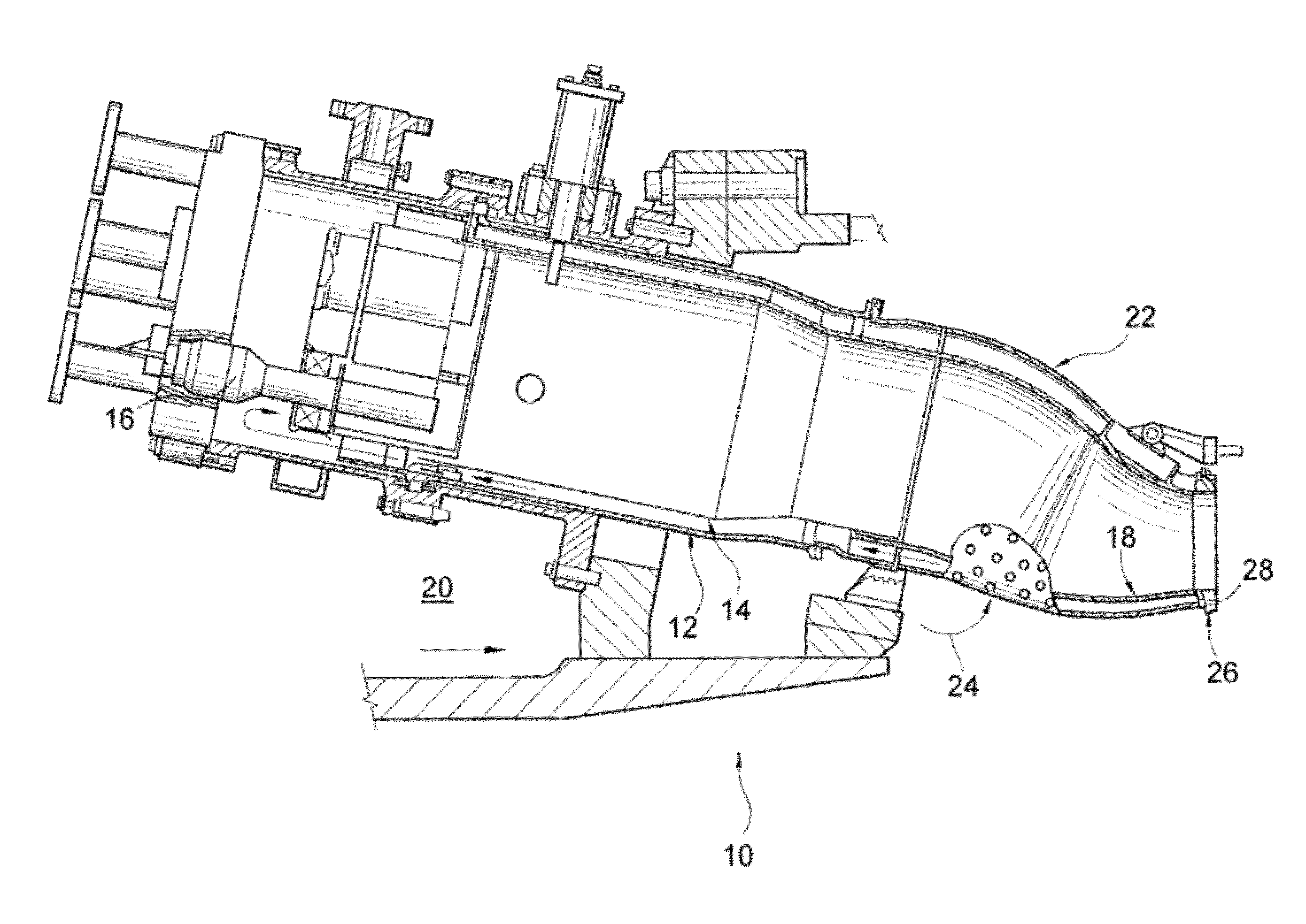
The aft frame 26 is subject to damage resulting from the combination of high temperatures and stresses that can lead to distortion and fatigue.
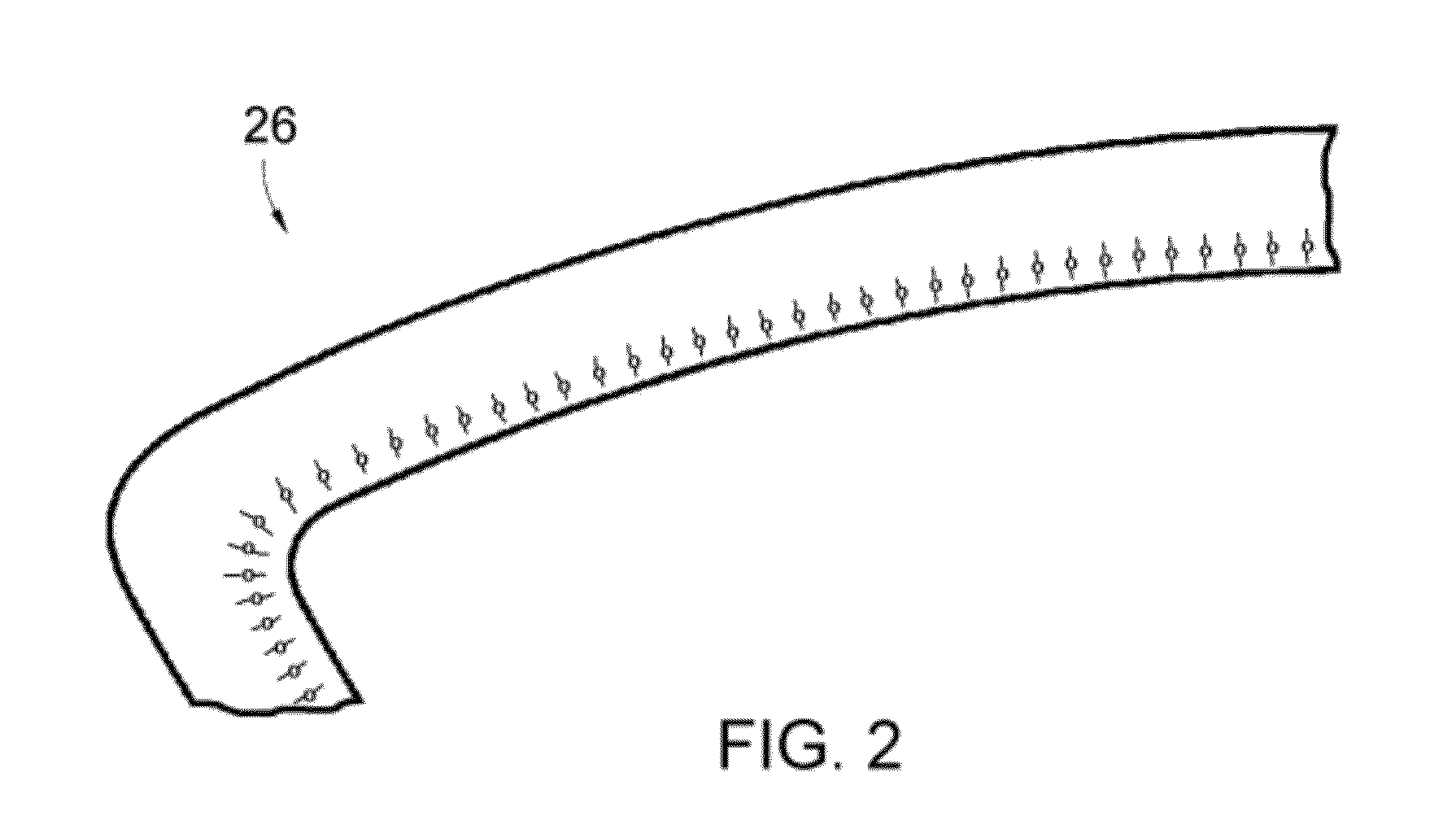
Because the cooling holes act as stress concentrators, the material of the frame 26 surrounding the holes can be particularly susceptible to cracking due to thermo-mechanical fatigue (TMF).
Removal of the TBC is performed because high heat inputs of traditional weld repair techniques lead to spallation of the TBC and / or mixing of the TBC material into the weld pool, resulting in weld cracking.
Following weld repair, the cooling holes must be re-drilled, an arduous and challenging task due to distortion of the transition piece 18 and its frame 26 during service.
Consequently, both processes are costly and time consuming.

Method used


Image

  • Method of repairing a transition piece of a gas turbine engine
  • Method of repairing a transition piece of a gas turbine engine
  • Method of repairing a transition piece of a gas turbine engine

Examples


Embodiment Construction

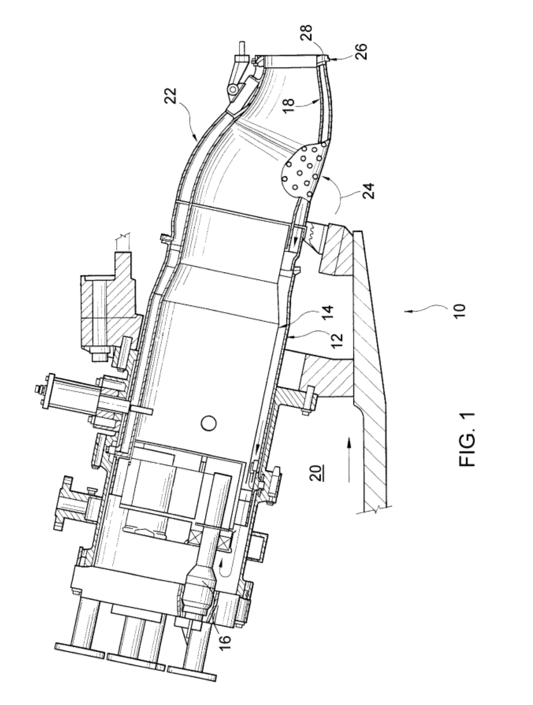
[0016]The present invention will be described with reference to the transition piece 18 of the industrial gas turbine 10 discussed above in reference to FIG. 1. As such, an exemplary transition piece 18 has an exterior surface surrounded by an impingement jacket 22 that is attached to the transition piece 18, an interior surface coated with a TBC or other coating system suitable for thermally insulating the interior surfaces of the transition piece 18, and an air-cooled aft frame 26 adapted to attach the transition piece 18 to the first stage of a turbine section of a gas turbine engine. Furthermore, transition pieces of interest to the invention may be formed of a variety of materials, particular examples of which include nickel-based alloys such as Nimonic C263, Hastelloy X, Inconel 617 and Udimet 500. Finally, the invention is directed to performing a weld repair of cracks that have propagated from cooling holes in a seal land 28 of the aft frame 26, for example, as schematically...


PUM

PropertyMeasurementUnit
Timeaaaaaaaaaa
Poweraaaaaaaaaa
Diameteraaaaaaaaaa

Abstract

A method of weld repairing an air-cooled aft frame of a transition piece of a gas turbine engine. The transition piece has an interior surface coated with a ceramic coating. The aft frame has a surface with cooling holes therein and from which cracks have propagated. The method includes removing the transition piece from the engine and, without removing the ceramic coating or the aft frame from the transition piece, weld repairing the cracks by performing a laser beam welding technique that deposits a filler material on the surface but does not close the cooling holes in the surface. The surface of the aft frame can be machined to remove excess filler material prior to re-installing the transition piece in a gas turbine engine.

Description

BACKGROUND OF THE INVENTION[0001]The present invention generally relates to welding methods for repairing components formed of high temperature alloys. More particularly, this invention is directed to a method for weld repairing an air-cooled transition piece of an industrial gas turbine engine, by which filling of cooling holes and spallation of a coating on the transition piece can be avoided.[0002]Superalloys are widely used to form components of turbomachinery, such as turbine components of industrial and aircraft gas turbine engines. Notable examples include turbine buckets (blades), nozzles (vanes), and combustor components such as liners, heatshields and transition pieces. Superalloy components are often formed by casting, and for some applications are preferably or necessarily fabricated by welding as a result of their complexity. Welding is also widely used as a method for repairing cracks and other surface discontinuities in superalloy components caused by thermal cycling ...

Claims


Application Information

Patent Timeline
IPC IPC(8): F01D25/00B23K26/00
CPCB23K26/34B23K26/3273B23K2201/001B23P6/045B23P2700/06B23P2700/13F01D9/023Y02T50/67Y02T50/675F05D2230/234F05D2230/30F05D2230/80F05D2230/10B23K26/3293B23K26/345B23K26/32B23K35/3033B23K35/304B23K26/342B23K2101/001B23K2101/34B23K2103/08B23K2103/52Y02T50/60
Inventor KOTTILINGAM, SRIKANTH CHANDRUDUMURPHY, GENE ARTHURBERKEBILE, MATTHEW PAUL
Owner GENERAL ELECTRIC CO
Learn More