
Universal mounting system for a handheld electronic device

a handheld electronic device and universal mounting technology, applied in the direction of portable computer details, electric apparatus casings/cabinets/drawers, instruments, etc., can solve the problems of insufficient and achieve the reduction or elimination of disadvantages and problems associated with previous devices and systems supporting the portability of handheld electronic devices

Inactive Publication Date: 2011-11-03
RAYTHEON CO
View PDF7 Cites 13 Cited by
  • Summary
  • Abstract
  • Description
  • Claims
  • Application Information

AI Technical Summary

Benefits of technology

[0004]In accordance with the teachings of the present disclosure, disadvantages and problems associated with previous devices and systems supporting the portability of handheld electronic devices can be reduced or eliminated by providing a universal mounting system for a handheld electronic device.
[0006]Various embodiments of the present disclosure may provide various technical advantages. One advantage is the ability to provide a universal mounting system for a handheld electronics device. Another advantage may include increasing the ease at which a handheld electronics device may be moved from one mounted location to another. A handheld electronics device may be mounted to a person such that the hands of the person may be freed to conduct tasks other than carrying the handheld electronics device, while the same device may be removed from the person and attached to a vehicle. Thus, other technical advantages may include the ability to easily and quickly mount a handheld electronics device in a convenient location in a vehicle or on a person and then transition the device to another location. The ability to use the same hardware to attach the device in multiple locations may provide flexibility, reduced cost, increased performance, efficiencies, and other benefits.

Problems solved by technology

Devices and systems supporting the portability of handheld electronic devices, however, have proven inadequate in various respects.

Method used


Image

  • Universal mounting system for a handheld electronic device
  • Universal mounting system for a handheld electronic device
  • Universal mounting system for a handheld electronic device

Examples


Embodiment Construction

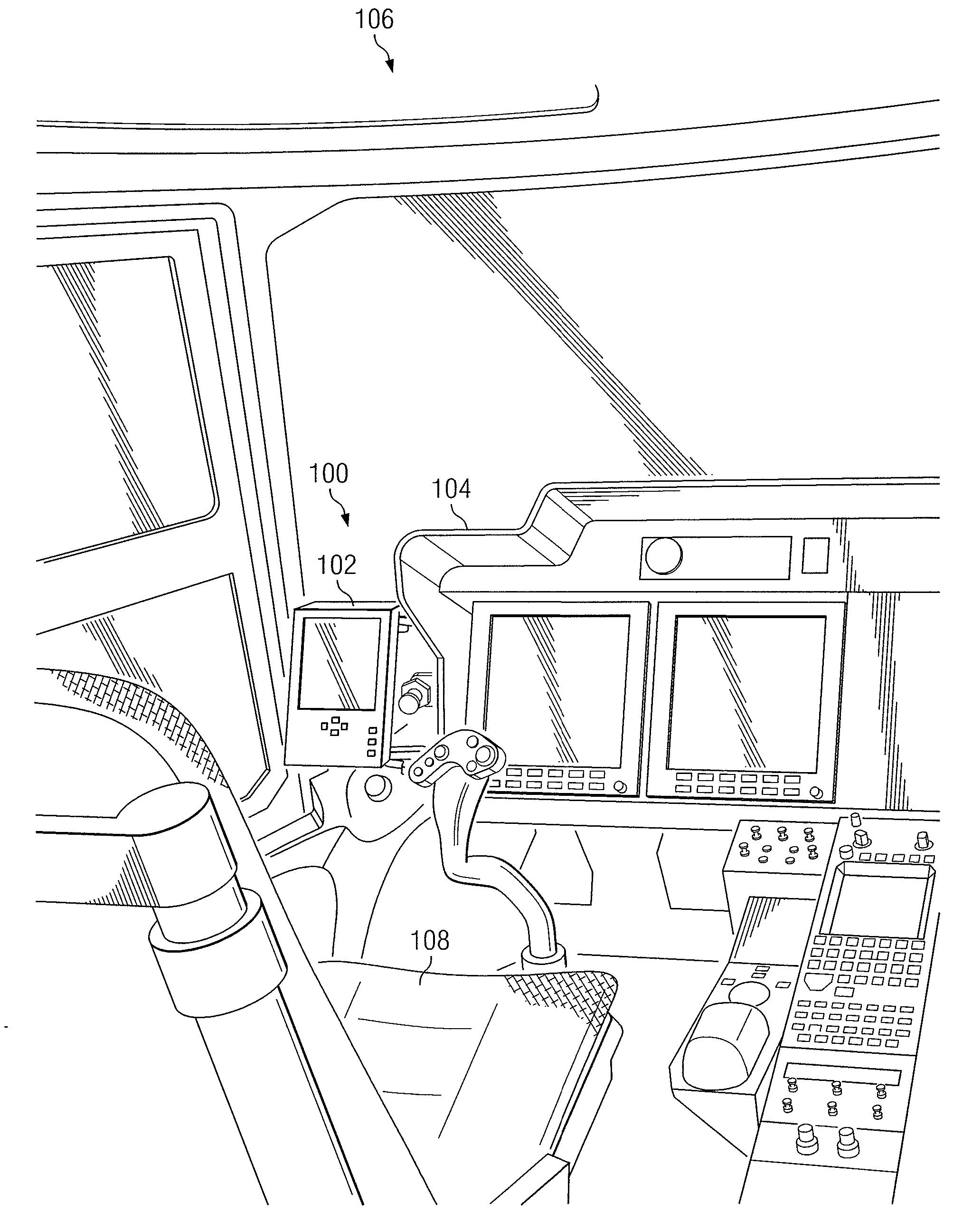
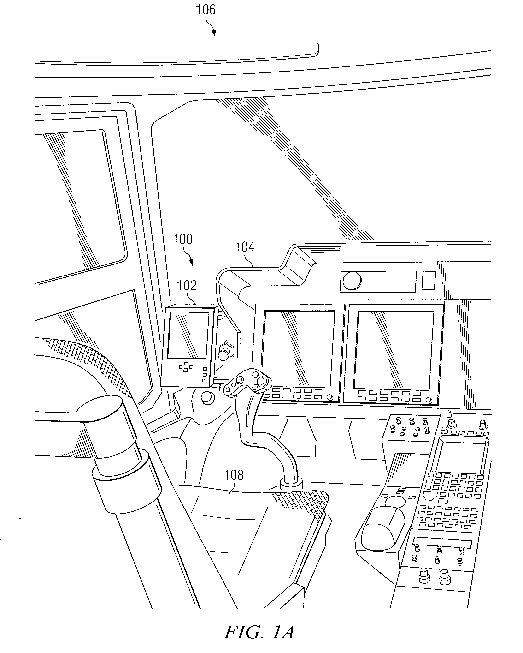
[0019]FIG. 1A is a front perspective view of an exemplary embodiment of a universal mounting system for a handheld electronic device mounted in a vehicle. As illustrated, universal mounting system 100 includes an electronic flight bag 102 mounted to a console 104 of an aircraft cockpit 106. The universal mounting system 100 may be configured in aircraft cockpit 106 such that electronic flight bag 102 faces the seat 108 of cockpit 106.

[0020]Generally, electronic flight bags 102 are computing devices that perform functionality associated with operation of an aircraft. In many cases, electronic flight bags 102 may include functionality that is useful to pilots during flight. For example, electronic flight bags 102 may include navigational charts to aid users with the development of flight plans. An electronic flight bag may include weather data, radar data, sensor data, and / or a real-time GPS navigational map indicating the instantaneous position of the aircraft. These electronic fligh...


PUM


Abstract

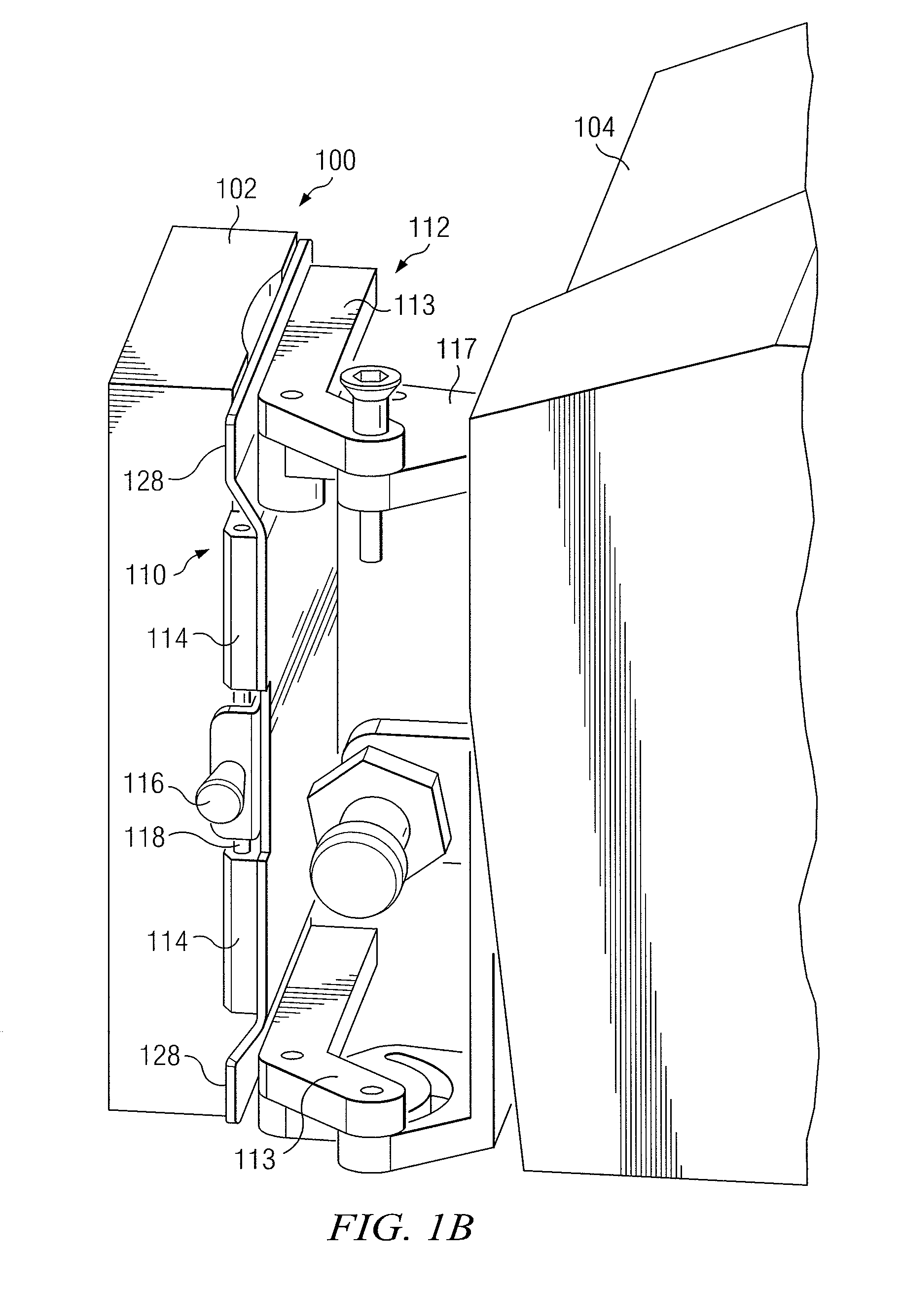
A universal mounting system for a handheld electronic device includes a handheld electronic device, a first mounting plate, and a second mounting plate. The handheld electronic device includes universal mounting members operable to mount to mounting plates. The first mounting plate includes first receiving members operable to detachably couple to the universal mounting members of the handheld electronic device. The first mounting plate also includes a fastener assembly operable to detachably couple the first mounting plate to a person. The second mounting plate includes second receiving members operable to detachably couple to the universal mounting members of the handheld electronic device. The second mounting plate also includes a connector assembly operable to attach the second mounting plate to a vehicle.

Description

GOVERNMENT RIGHTS[0001]This invention was made with government support under government contract number N00019-05-G-0008, MV-22 Netted Weather Trade Study. The government may have certain rights in this invention.TECHNICAL FIELD OF THE DISCLOSURE[0002]The present disclosure relates generally to handheld electronic devices, and, more particularly, to a universal mounting system for a handheld electronic device.BACKGROUND OF THE DISCLOSURE[0003]Over time, the use of handheld electronic devices has increased. For example, pilots use electronic flight bags to obtain and transmit information regarding flights. Accordingly, the need for more convenient and portable handheld electronics devices also has increased. Devices and systems supporting the portability of handheld electronic devices, however, have proven inadequate in various respects.SUMMARY OF THE DISCLOSURE[0004]In accordance with the teachings of the present disclosure, disadvantages and problems associated with previous device...

Claims


Application Information

Patent Timeline
IPC IPC(8): G05D1/00H05K7/00
CPCB60R11/02B60R2011/0007B60R2011/0059G06F1/1632B60R2011/0075G06F1/163B60R2011/0073
Inventor BOPP, JAYSON K.NELSON, ANDREW L.PALMER, SARAH L.
Owner RAYTHEON CO
Learn More