
Method and apparatus for measuring cantilever deflection in constrained spaces

a technology of constrained spaces and measurement methods, applied in the field of measuring equipment, can solve the problems of low signal-to-noise ratio, inability to investigate sub-cellular units, and system used so far with myofibrils

Active Publication Date: 2011-11-03
MCGILL UNIV
View PDF1 Cites 8 Cited by
  • Summary
  • Abstract
  • Description
  • Claims
  • Application Information

AI Technical Summary

Problems solved by technology

While these preparations allow measurements of force and muscle mechanics with high reproducibility, they do not allow the investigation of sub-cellular units—myofibrils, sarcomeres, molecules, etc.
Recently, studies with myofibrils and sub-cellular units of muscles have emerged—but giving the complexity of the experiments involving these structures, only a few laboratories around the world have this capability.
Furthermore, the systems used so far with myofibrils have several limitations, including a low signal-to-noise ratio, which limits detection of small differences in force observed in different conditions, a very low time resolution which limits the detection of molecular and kinetics events that may happen at the microsecond scale, and the incapacity of measuring force and imaging the myofibrils simultaneously with high spatial and temporal resolution.
However, all commercial AFMs are optimized for measuring forces which are perpendicular to the sample surface, which becomes a limitation when the forces of interest are parallel to the sample surface.
However, the difficulty in implementing the pendulum geometry lies in the constraint imposed by the focused incoming light or the diverging outgoing light which easily interferes with the sample surface.

Method used


Image

  • Method and apparatus for measuring cantilever deflection in constrained spaces
  • Method and apparatus for measuring cantilever deflection in constrained spaces
  • Method and apparatus for measuring cantilever deflection in constrained spaces

Examples


Embodiment Construction

[0029]The following description is presented to enable a person skilled in the art to make and use the invention. Modifications to the disclosed embodiments will be apparent to those skilled in the art and the general principals described herein may be applied to any apparatus making use of the optical beam deflection method without departing from the scope of the invention. Therefore the present invention is not intended to be limited to the embodiments disclosed herein, but is to be accorded the widest scope.

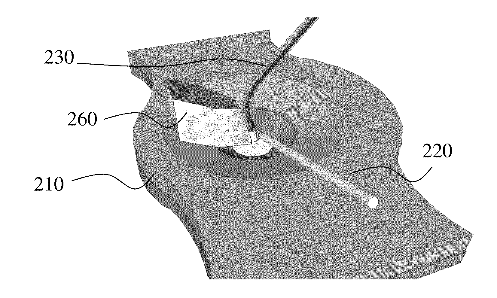
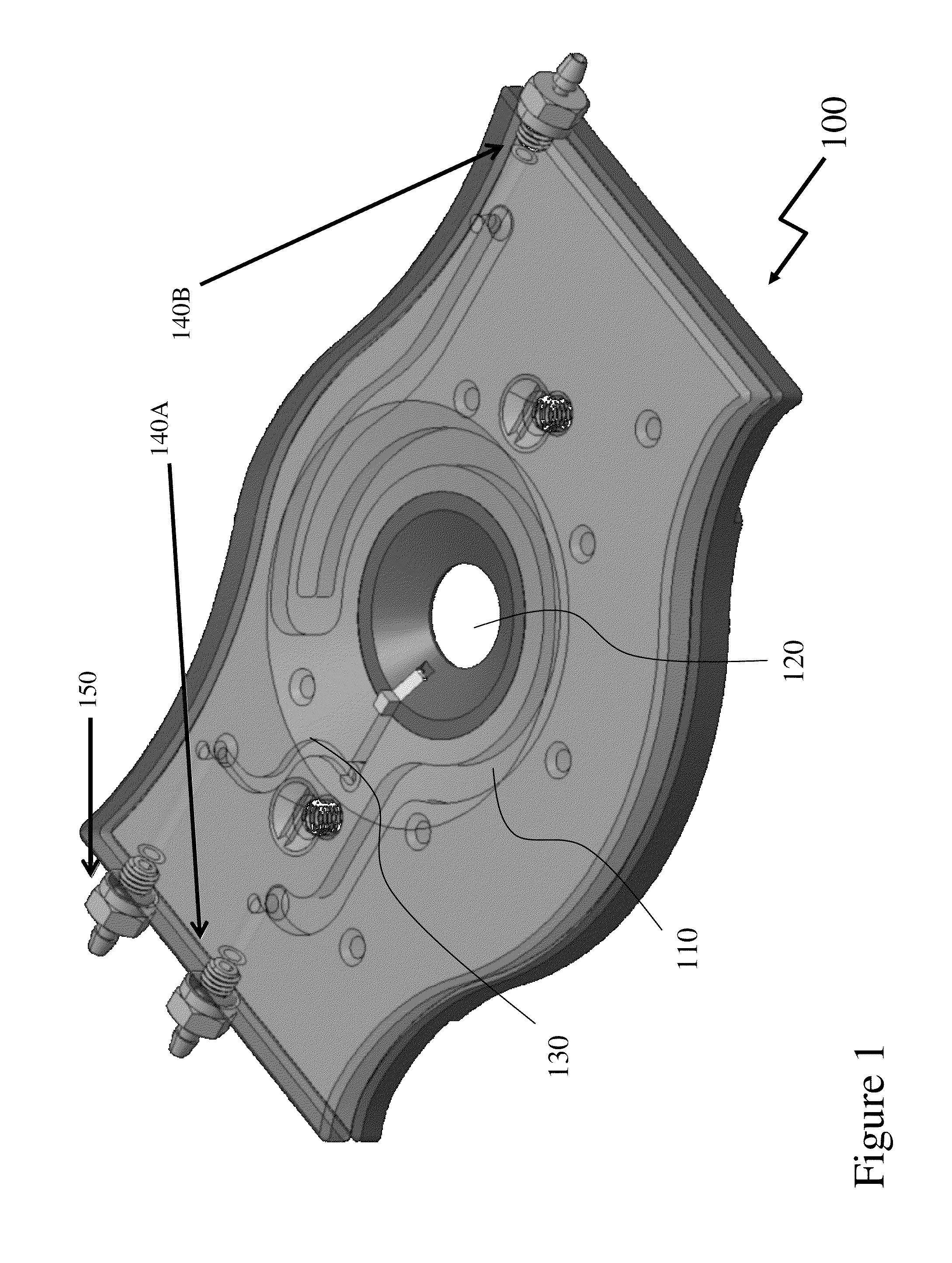
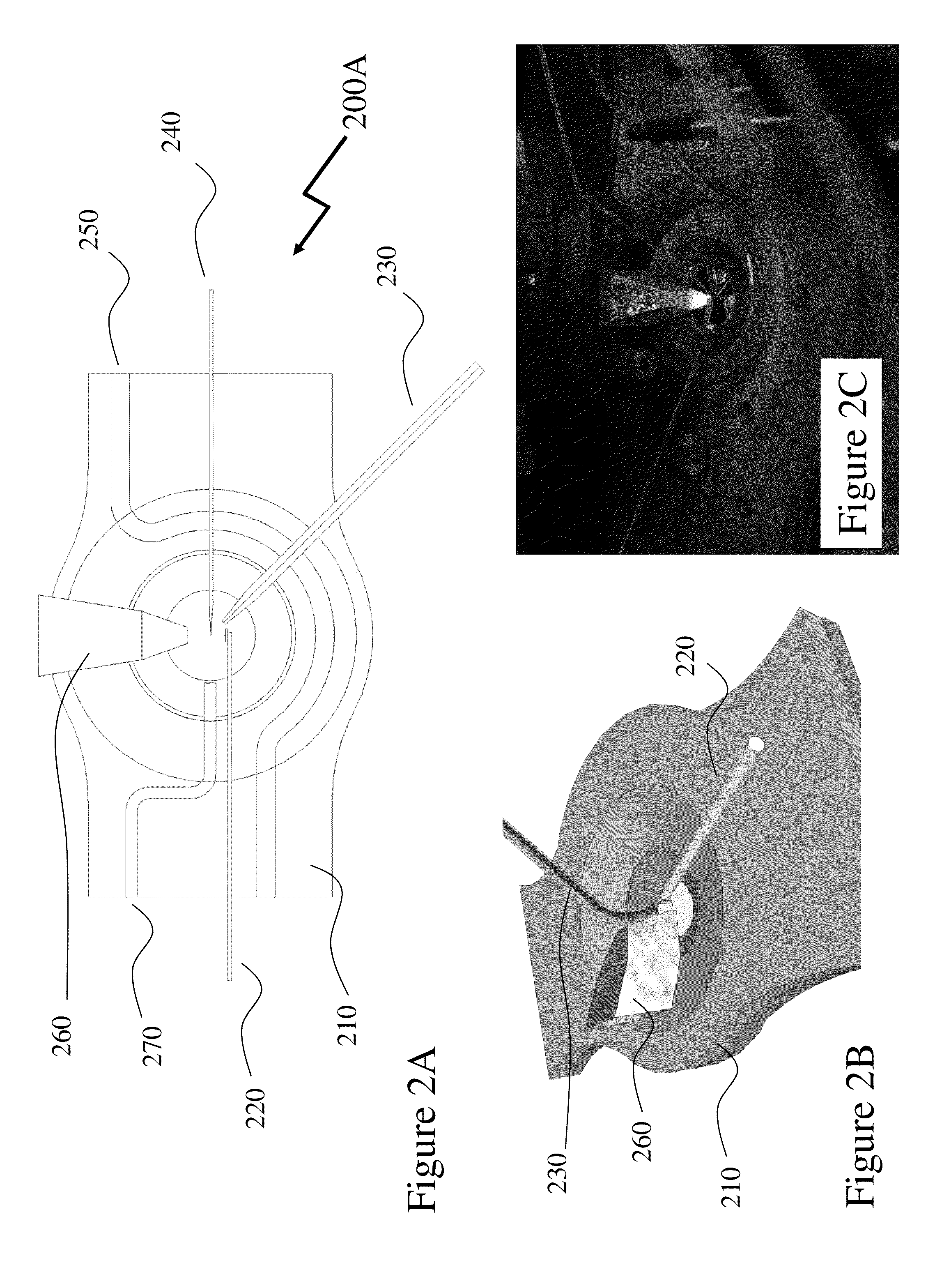
[0030]The invention presented hereinafter consists of a method and apparatus for guiding the light towards the cantilever and measuring the resulting optical beam deflection (OBD), referred to as an optical periscope. It enables the optical beam to be guided onto cantilevers within a constrained space; for example, it the cantilever is perpendicular to a large planar surface, the apparatus allows focusing light onto the cantilever while avoiding obstruction by the planar surfa...


PUM


Abstract

Atomic Force Microscopes (AFMs) allow forces within systems under observation to be probed from the piconewton forces of a single covalent bond to the forces exerted by cells in the micronewton range. The pendulum geometry prevents the snap-to-contact problem afflicting soft cantilevers in AFMs which enable attonewton force sensitivity. However, the microscopic length scale studies of cellular / subcellular forces parallel to the imaging plane of an optical microscope requires high sensitivity force measurements at high sampling frequencies despite the difficulties of implementing the pendulum geometry from constraints imposed by the focused incoming / outgoing light interfering with the sample surface. Additionally measurement systems for biological tissue samples in vitro must satisfy complex physical constraints to provide access to the vertical cantilever. Embodiments of the invention address these geometrical restrictions by exploiting optical periscope approaches that further allows multiple probes to be deployed and multiple optical beams within each probe.

Description

CROSS-REFERENCE TO RELATED APPLICATION[0001]This patent application claims the benefit of U.S. Provisional Patent Application 61 / 329,182 filed Apr. 29, 2010 entitled “Method and Apparatus for Measuring the Deflection on Cantilevers in Constrained Spaces.”FIELD OF THE INVENTION[0002]The invention relates to measurement equipment and more particularly to optical beam deflection apparatus.BACKGROUND[0003]Studies in the field of muscle Biophysics, Physiology, Nano-Scale Physics and Mechanics have been performed traditionally with preparations ranging from the whole muscle to isolated muscle cells. While these preparations allow measurements of force and muscle mechanics with high reproducibility, they do not allow the investigation of sub-cellular units—myofibrils, sarcomeres, molecules, etc. Recently, studies with myofibrils and sub-cellular units of muscles have emerged—but giving the complexity of the experiments involving these structures, only a few laboratories around the world ha...

Claims


Application Information

Patent Timeline
IPC IPC(8): G01Q20/02
CPCB82Y35/00G01Q20/00G01Q20/02
Inventor RASSIER, DILSONLABUDA, ALEKSANDER
Owner MCGILL UNIV
Learn More