Mounting clamps for coupling scopes to mounting rails of firearms

a technology for mounting clamps and scopes, which is applied in the direction of weapons, sighting devices, weapon components, etc., can solve the problems of significant compromise in rail engagement precision, and achieve the effects of reducing clamping loads, limiting or substantially eliminating stress concentrations in rails, and reducing applied stresses

Inactive Publication Date: 2011-11-10
KARAGIAS THEODORE
View PDF4 Cites 17 Cited by
  • Summary
  • Abstract
  • Description
  • Claims
  • Application Information

AI Technical Summary

Benefits of technology

[0006]At least some embodiments disclosed herein are directed to a sighting assembly with at least one mounting clamp configured to grip a telescopic sight. The mounting clamp can be coupled to a mounting rail without creating appreciable localized stresses in the mounting rail and / or mounting clamp so as to avoid or limit damage to the mounting rail and / or mounting clamp. The mounting clamp can be a scope ring or other type of clamp for holding the telescopic sight, or other type of sighting device or accessory (e.g., a handle, a bipod, sling attachment device or point, a light, etc.).
[0007]A mounting clamp has, in some embodiments, one or more crowned portions for physically contacting a mounting rail. The crowned portions cooperate to grip the rail and to minimize, limit, or substantially eliminate stress concentrations in the rail.
[0008]In some embodiments, a rail clamp includes a plurality of crowned surfaces surrounding a mounting rail channel which is sized to receive a mounting rail. The crowned surfaces can deform due to applied loads to keep stresses at or below a desired level. For example, the crowned surfaces can flatten out to keep stresses in the mounting clamp and / or mounting rail below the yield strength of the mounting clamp or the yield strength of the mounting rail, or both.
[0009]In some embodiments, a mounting clamp has one or more crowned portions positioned to engage a mounting rail. When installed, the crowned portions distribute clamping forces along a section of the rail. In certain embodiments, the crowned portions extend along most or substantially all of a length of a mounting rail channel. A mounting rail can be inserted into the mounting rail channel of the mounting clamp. In some embodiments, the crowned portions are sufficiently curved so as to elastically deform to accommodate relatively high clamping loads, thereby reducing applied stresses.
[0010]In some embodiments, a scope mounting clamp is coupleable to a firearm. The scope mounting clamp includes a plurality of deformable portions that are configured to physically contact and grip a mounting rail. Non-planar surfaces of the deformable portions help minimize, limit, or substantially eliminate edge loading. In some embodiments, the deformable portions are crowned regions of the mounting clamp surrounding a channel or opening in which the mounting rail can be placed.

Problems solved by technology

Such rail clamps thus often compromise rail engagement precision.
If the scope ring is repeatedly removed and reinstalled, rail engagement precision can be significantly compromised.

Method used


Image

  • Mounting clamps for coupling scopes to mounting rails of firearms
  • Mounting clamps for coupling scopes to mounting rails of firearms
  • Mounting clamps for coupling scopes to mounting rails of firearms

Examples


Embodiment Construction

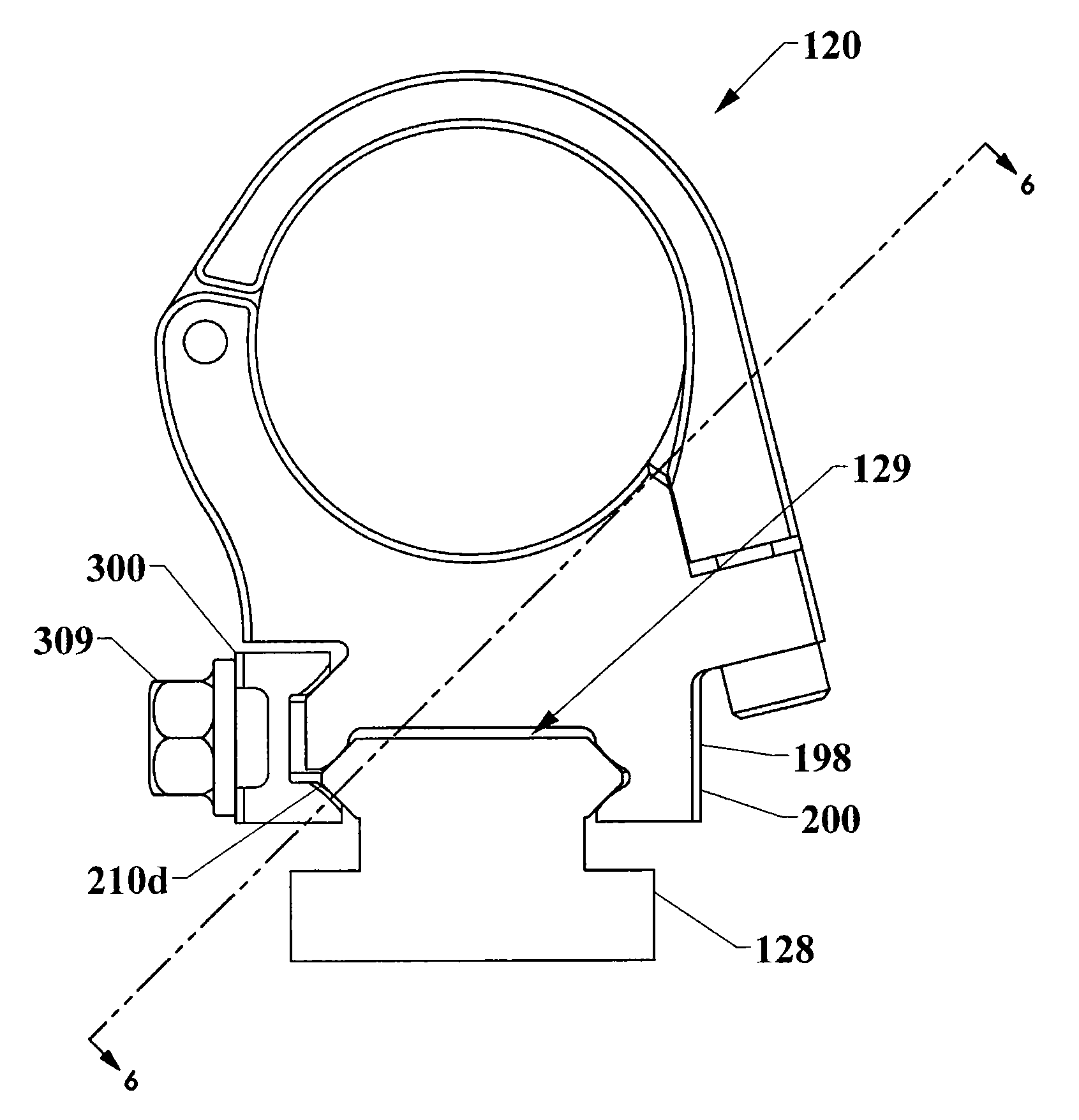
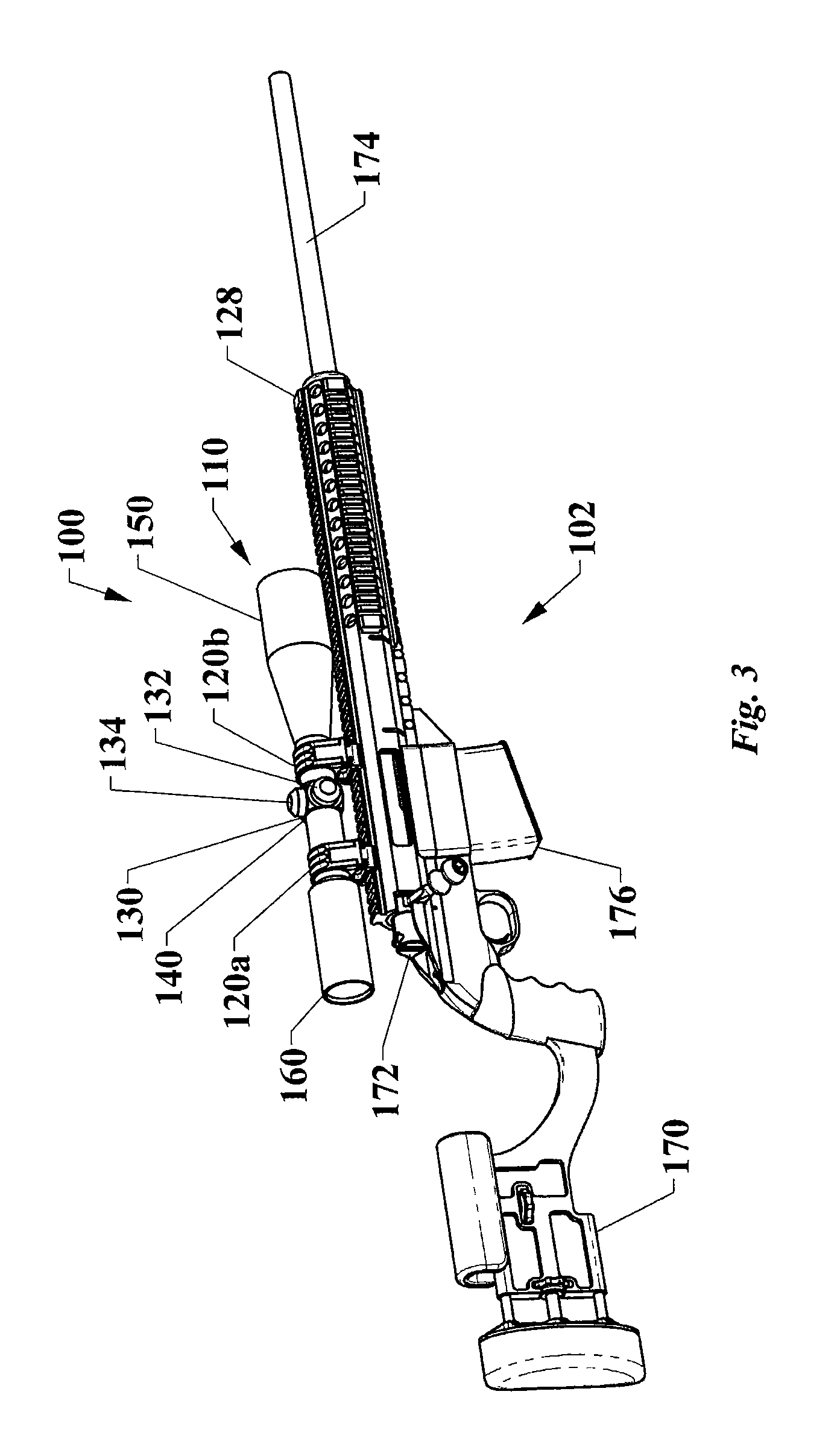
[0028]FIG. 3 shows a viewing assembly 100 mounted on a firearm 102. The viewing assembly 100 includes a sight 110 and a pair of mounting clamps 120a, 120b (collectively “120”). The mounting clamps 120 are coupled to a mounting rail 128. To move the scope 110, the mounting clamps 120 can release the mounting rail 128 and can be coupled at appropriate locations along the rail 128. The mounting clamps 120 can provide relatively large clamping forces without damaging (e.g., marring, denting, bending, scratching, or otherwise permanently deforming) the clamps 120 and / or the mounting rail 128.

[0029]The mounting rail 128 can be an accessory rail or other type of rail or feature to which components can be coupled. The mounting clamps 120 may be repeatedly removed and reinstalled without re-zeroing (recalibration) of firearm 102, even if the mounting rail 128 is undersized or oversized with respect to a rail channel 129 (FIG. 4).

[0030]The firearm 102 of FIG. 3 is a rifle with a butt stock 17...


PUM


Abstract

A sighting assembly for a firearm includes a scope and a mounting clamp. The mounting clamp includes a ring cap and a ring base that cooperate to surround and hold the scope. The mounting clamp has a rail clamp that includes a plurality of crowned portions that are configured to physically contact and grip a mounting rail.

Description

CROSS-REFERENCE TO RELATED APPLICATION[0001]This application claims the benefit under 35 U.S.C. §119(e) of U.S. Provisional Patent Application No. 61 / 294,407 filed Jan. 12, 2010, where this provisional application is incorporated herein by reference in its entirety.BACKGROUND[0002]1. Technical Field[0003]The present invention relates generally to mounting clamps for firearms. More specifically, the invention relates to mounting clamps capable of coupling an accessory to a mounting rail of a firearm.[0004]2. Description of the Related Art[0005]Telescopic sights are used in a wide range of different fields. Telescopic sights, such as scopes, are often used to aim firearms, such as rifles or handguns. A user can peer through the scope to view a target up close. Conventional scope rings for holding scopes are often coupled to accessory rails of firearms. Unfortunately, these scope rings have flat surfaces that physically contact the accessory rails and result in edge loading. FIGS. 1 an...

Claims


Application Information

Patent Timeline
Patent Type & Authority Applications(United States)
IPC IPC(8): F41G1/387
CPCF41G11/003F41G1/387
Inventor KARAGIAS, THEODORE
Owner KARAGIAS THEODORE
Why Eureka
Try Eureka