Tower structure

Inactive Publication Date: 2011-11-10
ELECTRO MECHANICAL INDS
View PDF63 Cites 44 Cited by
  • Summary
  • Abstract
  • Description
  • Claims
  • Application Information

AI Technical Summary

Problems solved by technology

The installation of these tower structures is costly since heavy equipment must be purchased or rented and transferred to the erection site.
Further, the installation procedure can take many days.
Additionally, once the

Method used


Image

  • Tower structure
  • Tower structure
  • Tower structure

Examples


Embodiment Construction

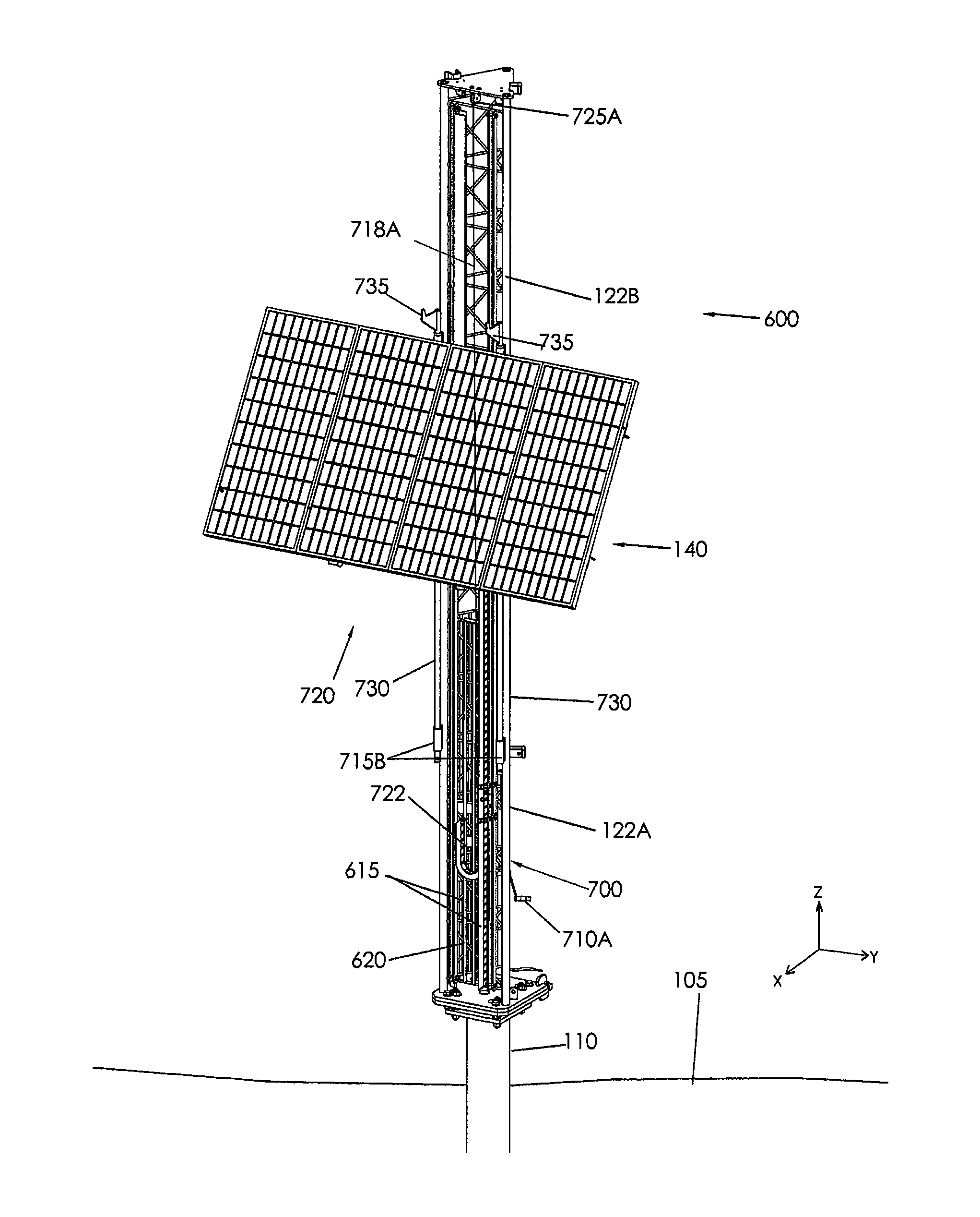
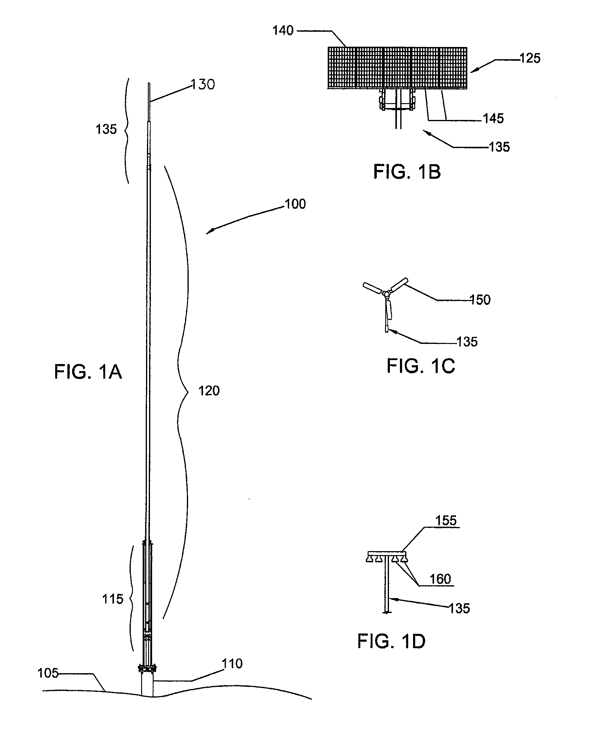
[0036]Embodiments of the invention generally relate to a tower structure utilized to support aerial components, and methods of erecting and / or servicing the tower structure. The aerial components as described herein may include power generation devices, power transmission devices, lighting devices, signal lights, communication devices, global positioning devices, satellite or microwave dishes, surveillance cameras, motion detectors, as well as flags, banners, signage, among other devices or articles adapted to be supported above the ground. Power generation devices include solar cells or solar arrays, wind generators, as well as other energy generators or energy collectors.

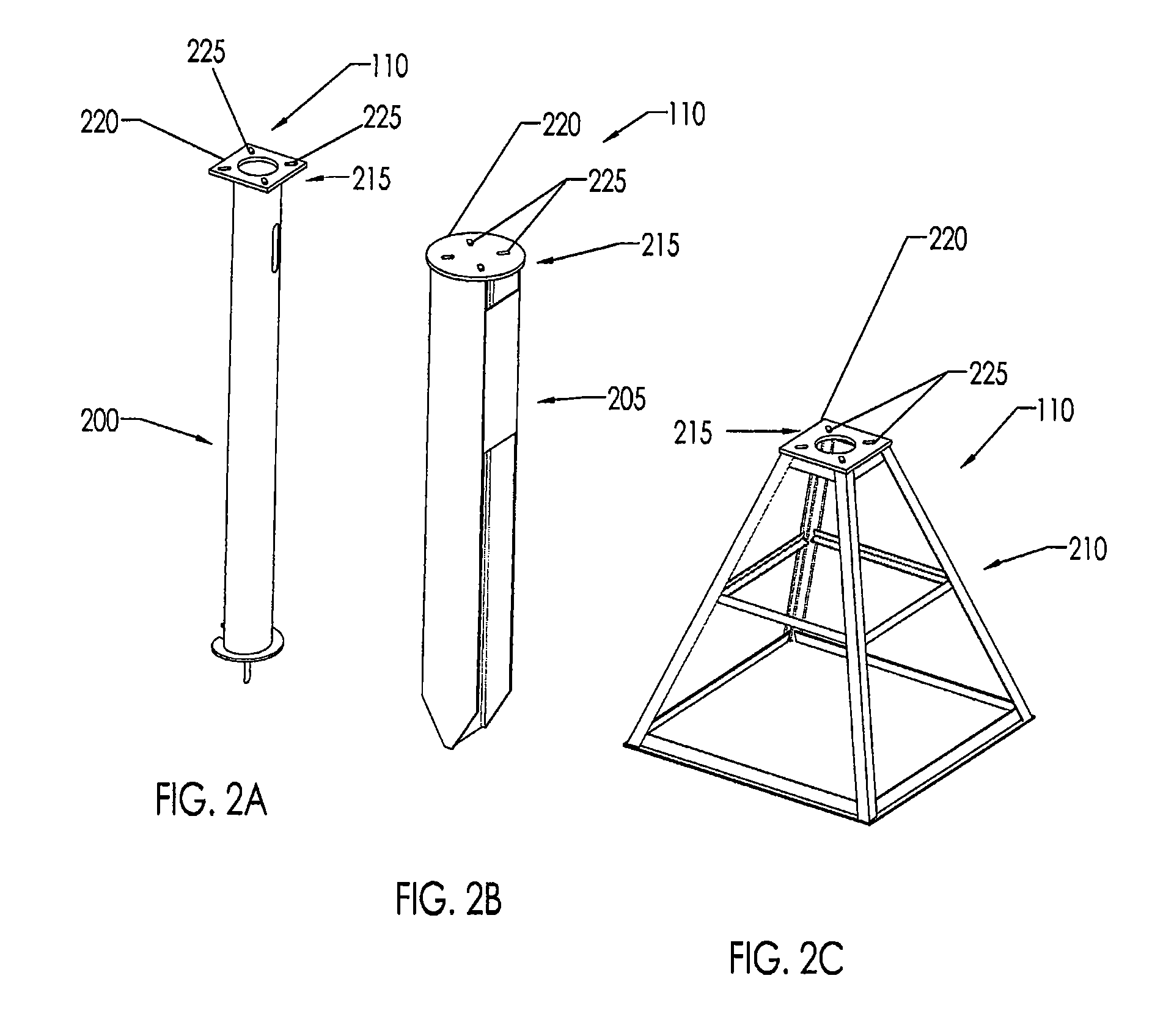
[0037]FIG. 1A is an isometric elevation view of one embodiment of a tower structure 100 coupled to the ground 105. The tower structure 100 includes a base 110 that is coupled to the ground 105, an intermediate structure 115 coupled to the base 110 and a mast structure 120 coupled to the intermediate structure 115....


PUM


Abstract

Embodiments of the invention generally relate a method and apparatus for a tower structure. In one embodiment, the tower structure comprises a first base plate comprising a first hinge device, a first structural section having a first side and a second side, the first structural section coupled to a second base plate comprising a second hinge device, a second structural section coupled to the first structural section, and an aerial component coupled to the second structural section, wherein the first structural section is rotatable relative to the first base plate in a first rotational axis, the second structural section is rotatable relative to the first structural section in a second rotational axis, and at least a portion of the second structural section is received in a channel formed in the first side of the first structural section when the first structural section and the second structural section are substantially parallel.

Description

CROSS-REFERENCE TO RELATED APPLICATIONS[0001]This application claims benefit of U.S. Provisional Patent Application Ser. No. 61 / 322,706, filed Apr. 9, 2010, which is incorporated herein by reference.BACKGROUND OF THE INVENTION[0002]1. Field of the Invention[0003]Embodiments of the invention generally relate to tower structure apparatus utilized for power generation, communications, lighting, among other uses, and methods of erecting and / or servicing tower structure apparatus.[0004]2. Description of the Related Art[0005]Tower structures utilized for supporting aerial components, such as lighting, antennas, solar modules and wind generators, are known. The tower structures generally include a pole and / or a truss structure that is coupled to the ground. The tower structures may support the aerial components a few feet above the ground to thousands of feet above the ground and are designed to withstand high winds.[0006]Conventional tower structures above about 15 feet tall are typically...

Claims


Application Information

Patent Timeline
IPC IPC(8): H01Q1/22E04H12/34E04H12/00
CPCE04H12/10E04H12/187F24J2/523F24J2/5406F24J2/5232H01Q1/1242Y02E10/728Y02E10/47H01Q1/08E04H12/182E04H12/2261E04H12/345E04H2012/006F24S25/10F24S25/12F24S30/422
Inventor EGAN, FALLON M.GUTIERREZ, CLAUDIO J.SANCHEZ, CHRISTOVALWEISBROD, PATRICK M.
Owner ELECTRO MECHANICAL INDS
Why Eureka
Try Eureka