Centre drilling/turning tool holder

Inactive Publication Date: 2011-11-10
HSIEH CHUN TA
View PDF13 Cites 3 Cited by
  • Summary
  • Abstract
  • Description
  • Claims
  • Application Information

AI Technical Summary

Benefits of technology

[0010]One object of the invention is to provide a centre drilling/turning tool holder which saves operation time of a pillar

Problems solved by technology

This process needs multiple times of centre-point correction which takes time and may generate correction errors.
It takes time to perform such a withdrawing process.
Whenever

Method used


Image

  • Centre drilling/turning tool holder
  • Centre drilling/turning tool holder
  • Centre drilling/turning tool holder

Examples


Embodiment Construction

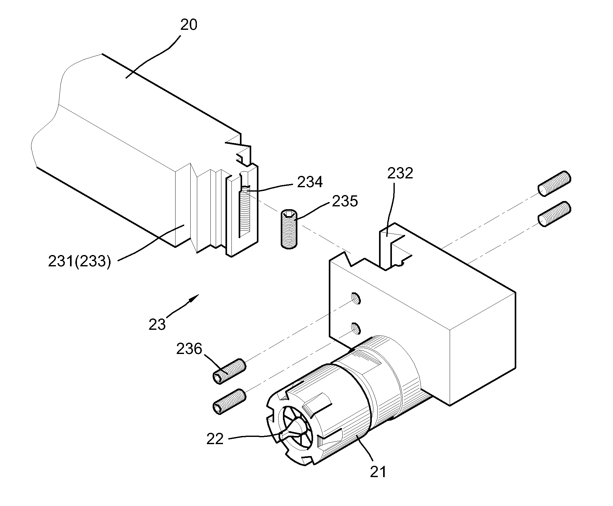
[0031]As shown in 5 through FIG. 9, a centre drilling / turning tool holder of the invention has a plurality of tool holders 20 on a lathe 10 which mainly include a stock receiver 11, a pillar holder 12 and a tail section 13. The stock receiver 11 is a movable receiver to position a workpiece 30. Opposite to the stock receiver 11 is the tail section 13 which is also movable and has a top pin 131 at its front for urging the workpiece 30 against the stock receiver 11. The pillar holder 12 locates inside the stock receiver 11 and the tail section 13 in a manner of being able to spin and move. A plurality of positioning means surrounds the pillar holder 12 in order to position the tools or drill heads which are used to cut or drill the workpieces 30. The positioning means on the pillar holder 12 has a plurality of column clippers 121 and a plurality of clamping slots 122, as shown in FIG. 7.

[0032]In the invention, at least one tool holder 20 is positioned on the pillar holder 12. The tool...


PUM


Abstract

The invention discloses a centre drilling/turning tool holder including a stock receiver, a pillar holder, and a tail section. The stock receiver is used to position a workpiece. The pillar holder is able to move and spin, and has a plurality of positioning means for positioning a tool. The tail section is able to move and has a top pin for urging the workpiece. The pillar holder positions at least one tool holder. One side of the tool holder positions one tool. The configuration of the tool holder allows the pillar holder to avoid from contacting the tail section so that operation time is saved and centre-point correction becomes more efficient.

Description

BACKGROUND OF THE INVENTION[0001]1. Field of the Invention[0002]The present invention relates to lathe field. More specifically, it relates to a centre drilling / turning tool holder which saves operation time of a pillar holder and reduces the number of centre-point correction, bringing efficiency and preventing error in correction when in use.[0003]2. Related Prior Art[0004]FIG. 1 through FIG. 4 shows the operation of processing a workpiece by a lathe. A stock receiver 1 clips a workpiece 2. A pillar holder 3 moves to allow a drill head 4 of the pillar holder 3 aligns with centre of the worpiece 2 and then drills the workpiece 2 until a recession is formed on the workpiece 2. After the pillar holder 3 withdraws back, the workpiece 2 moves into a tail section 5. A top pin 6 of the tail section 5 urges against the recession of the workpiece 2 to further position the workpiece 2. In turns, the workpiece 2 moves to the pillar holder 3 so that the tool of the pillar holder 3 can contact ...

Claims


Application Information

Patent Timeline
IPC IPC(8): B23B29/12
CPCB23B3/162B23B29/08Y10T82/2585B23B2260/04B23B49/04
Inventor HSIEH, CHUN-TA
Owner HSIEH CHUN TA
Why Eureka
Try Eureka