Air blowing device

Inactive Publication Date: 2011-11-10
HOWA PLASTICS CO LTD
View PDF4 Cites 0 Cited by
  • Summary
  • Abstract
  • Description
  • Claims
  • Application Information

AI Technical Summary

Benefits of technology

[0005]The present invention has been achieved to solve the above-mentioned problems. Specifically, an object of the invention is to provide an air blowing device which can be manufactured at low cost by reducing the number of steps of manufacture and man-hours of assembly. Another object of the invention is to provide an air blowing device which exhibits enhanced appearance of the closing surface at the time of air supply shutoff.
[0056]Further, as schematically shown in FIG. 3(a), in the case of no provision of the above-mentioned inclined portion on the inner circumferential surface of a front-end portion of the tubular body, when the airflow adjustment member is in the wind direction adjusting state, an airflow is blown out in a direction along the axis of the tubular body from a space between “the airflow direction adjustment plate located most distant from the closing airflow direction adjustment plate” and “the inner surface of the tubular body” (see arrow B). This airflow interferes with an airflow which has passed through the airflow adjustment member and is blown out in a direction corresponding to the angle θ. In contrast, as schematically shown in FIG. 3(b), through provision of the above-mentioned inclined portion 21e, the above-mentioned space can be narrowed. Thus, the amount of air blown out from the space can be reduced. As a result, the airflow passing through the airflow adjustment member can be blown out more reliably in the direction corresponding to the angle θ.

Problems solved by technology

However, since these members (airflow direction adjustment plates, connection members, pivot members, etc.) are manufactured independently, the number of steps required for manufacture of the air blowing device is large.
Furthermore, since the air blowing device is manufactured through sequential assembly of the members, the assembly work is complicated and time-consuming.
Therefore, the air blowing device involves a problem of high cost of manufacture.
The boundary line impairs the appearance of the air blowing device at the time of air supply shutoff.

Method used


Image

  • Air blowing device
  • Air blowing device
  • Air blowing device

Examples


Embodiment Construction

[0070]An embodiment of an air blowing device of the present invention will next be described with reference to the drawings.

[0071]FIG. 4 is a perspective view showing an embodiment of an air blowing device of the present invention. FIG. 5 is an exploded perspective view of the air blowing device shown in FIG. 4. FIGS. 6 and 7 are sectional views of the air blowing device as cut by a plane along line 1-1 of FIG. 4.

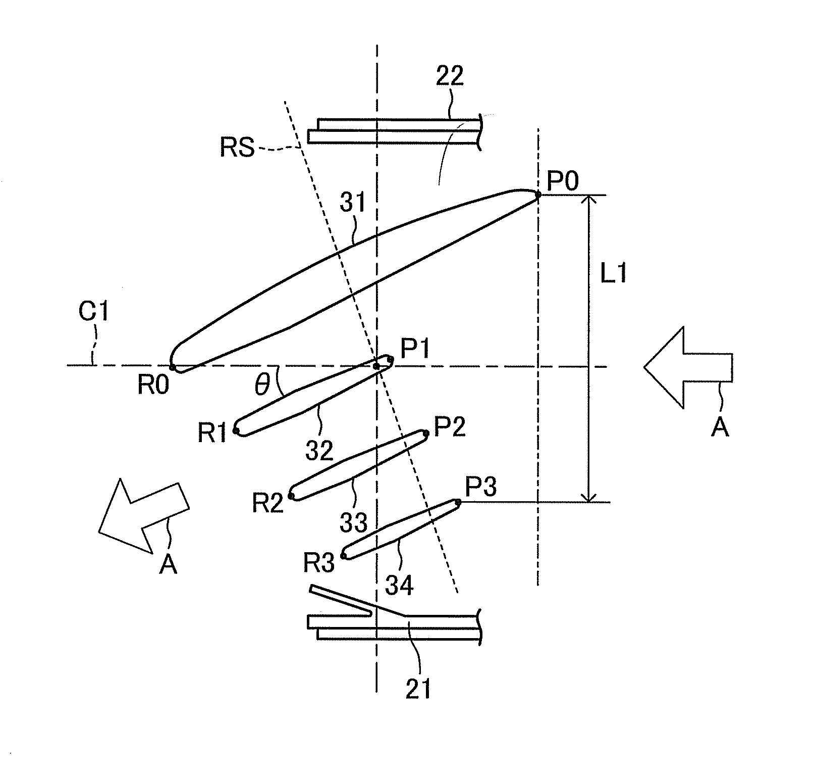
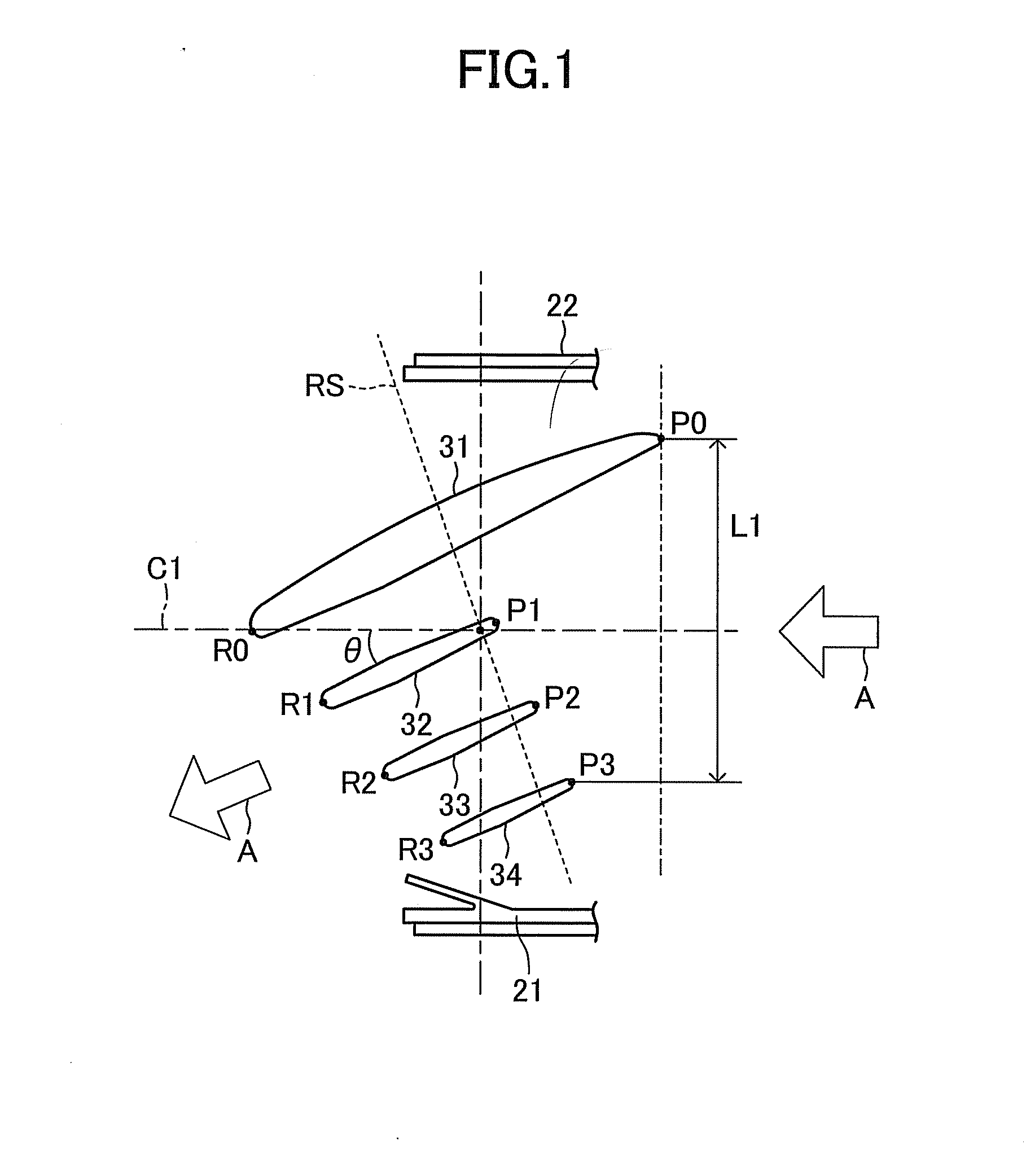
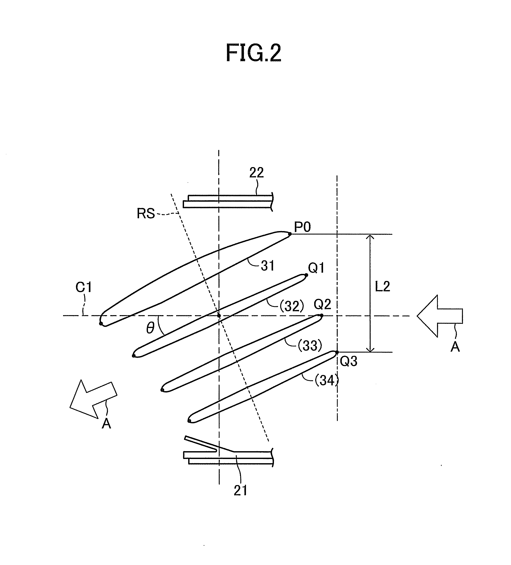
[0072]As shown in FIG. 4, an air blowing device 10 includes a tubular body 20 and an airflow adjustment member 30 which is supported in the interior of the tubular body 20.

[0073]As shown in FIG. 5, the tubular body 20 is composed of: an inner register 21 for supporting the airflow adjustment member 30; a cylindrical retainer 22 to which the inner register 21 is fitted; and an annular bezel 23 which is fitted to a front-end portion of the retainer 22. The inner register 21, the retainer 22, and the bezel 23 are coaxially disposed. As indicated by arrows A in FIGS. 4 and 5, a...


PUM


Abstract

An airflow adjustment member includes the following unitarily formed members: a closing airflow direction adjustment plate, a plurality of rear airflow direction adjustment plates (a first rear airflow direction adjustment plate, a second rear airflow direction adjustment plate, and a third rear airflow direction adjustment plate), and connection members (a first connection member and a second connection member). When air blown out from an air blowing device is to be shut off, an opening portion of the air blowing device is closed by a single closing airflow direction adjustment plate. The positions of front-end portions of the rear airflow direction adjustment plates are determined according to distances of the rear airflow direction adjustment plates from the closing airflow direction adjustment plate.

Description

TECHNICAL FIELD[0001]The present invention relates to an air blowing device for use in an air conditioner of an automobile or the like.BACKGROUND ART[0002]Conventionally, there is proposed an air blowing device for switching between supply and shutoff of cooled or heated air or the like to the interior of an automobile or the like and for adjusting the direction of an airflow in the case of supply of cooled or heated air or the like, for the purpose of adjusting the interior atmosphere of the automobile or the like. One conventional air blowing device includes a tubular body having a circular cross section, and a plurality of airflow direction adjustment plates disposed within the tubular body. The air blowing device is configured to change the blowing direction of airflow by adjusting the angle of the plurality of airflow direction adjustment plates (refer to, for example, Japanese Patent Application Laid-Open No. 2007-55396).DISCLOSURE OF THE INVENTION[0003]In the above-mentioned ...

Claims


Application Information

Patent Timeline
IPC IPC(8): F16L9/00
CPCB60H1/3428F24F13/075F24F13/06B60H2001/3492
Inventor HIBINO, YOSHIMITSU
Owner HOWA PLASTICS CO LTD
Why Eureka
Try Eureka