Self-inflating tire assembly

a tire assembly and self-inflating technology, which is applied in the direction of inflatable tyres, tire measurements, vehicle components, etc., can solve the problems of reducing vehicle braking and handling performance, reducing tire life, and reducing fuel economy, so as to improve traction

Active Publication Date: 2011-11-10
THE GOODYEAR TIRE & RUBBER CO
View PDF1 Cites 62 Cited by
  • Summary
  • Abstract
  • Description
  • Claims
  • Application Information

AI Technical Summary

Benefits of technology

[0024]“Sipe” means small slots molded into the tread elements of the tire that subdivide the tread surface and improve traction, sipes are generally narrow in width and close in the tires footprint as opposed to grooves that remain open in the tire's footprint.

Problems solved by technology

Accordingly, drivers must repeatedly act to maintain tire pressures or they will see reduced fuel economy, tire life and reduced vehicle braking and handling performance.
Such systems, however, remain dependant upon the driver taking remedial action when warned to re-inflate a tire to recommended pressure.

Method used


Image

  • Self-inflating tire assembly
  • Self-inflating tire assembly
  • Self-inflating tire assembly

Examples


Embodiment Construction

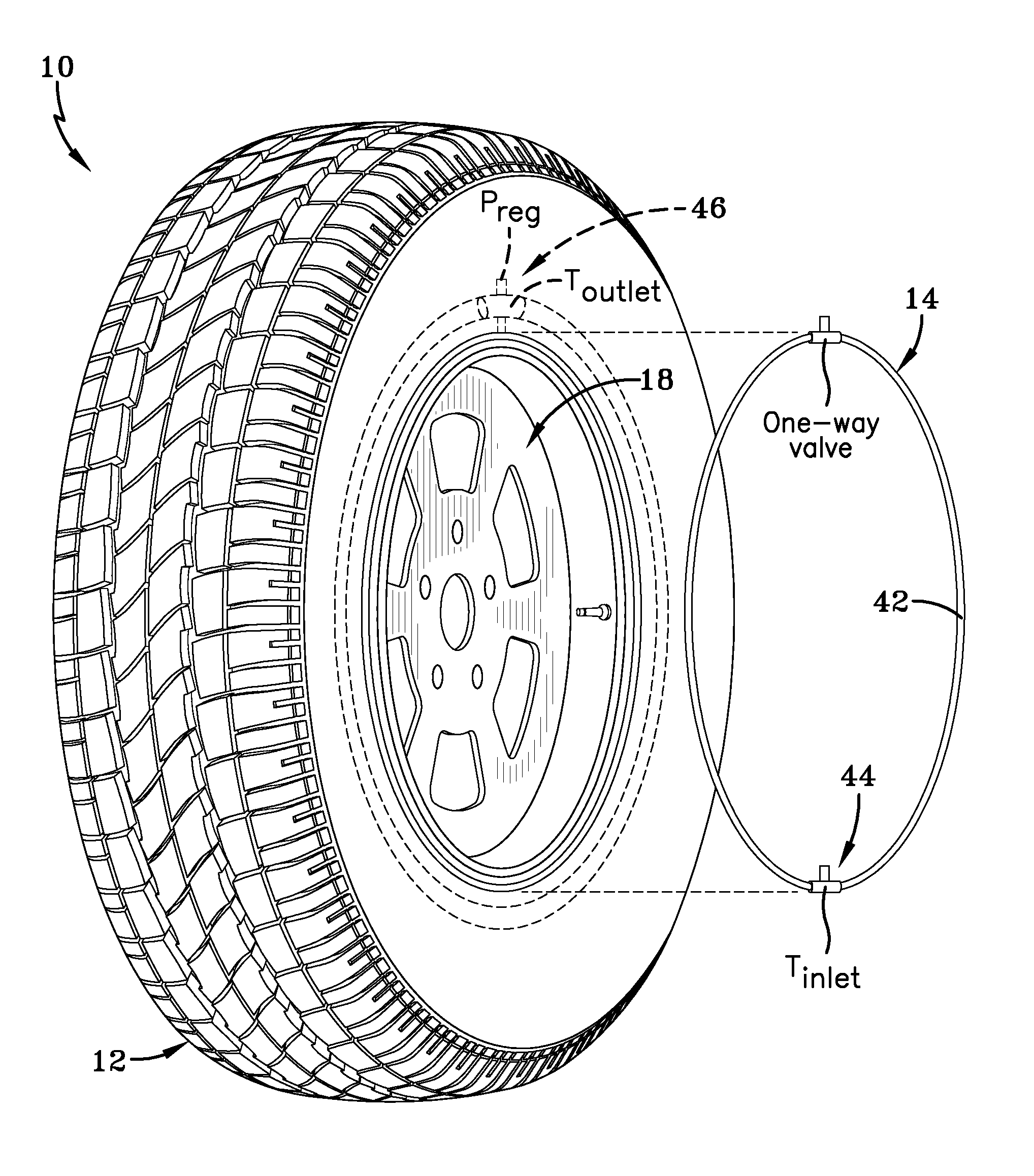
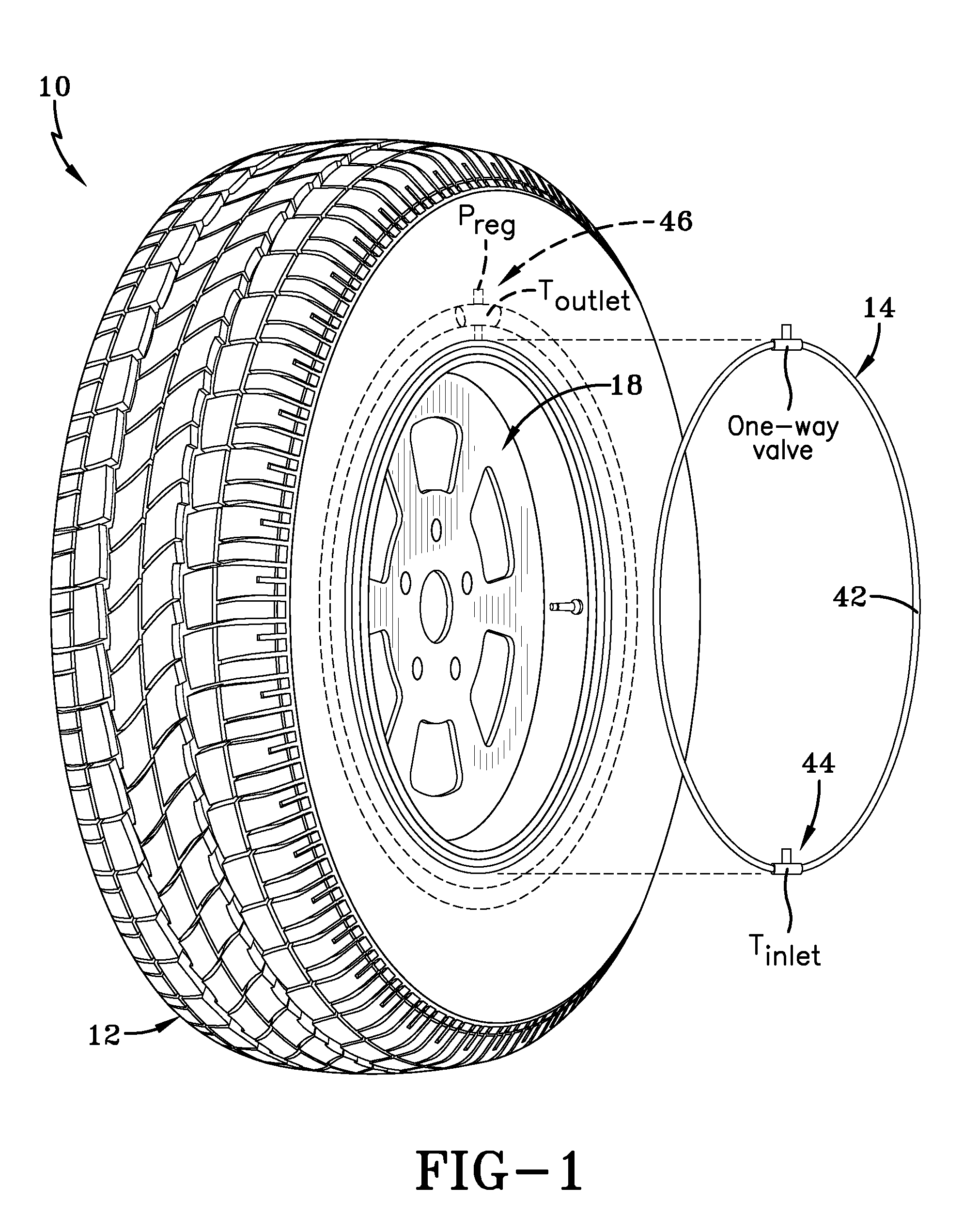
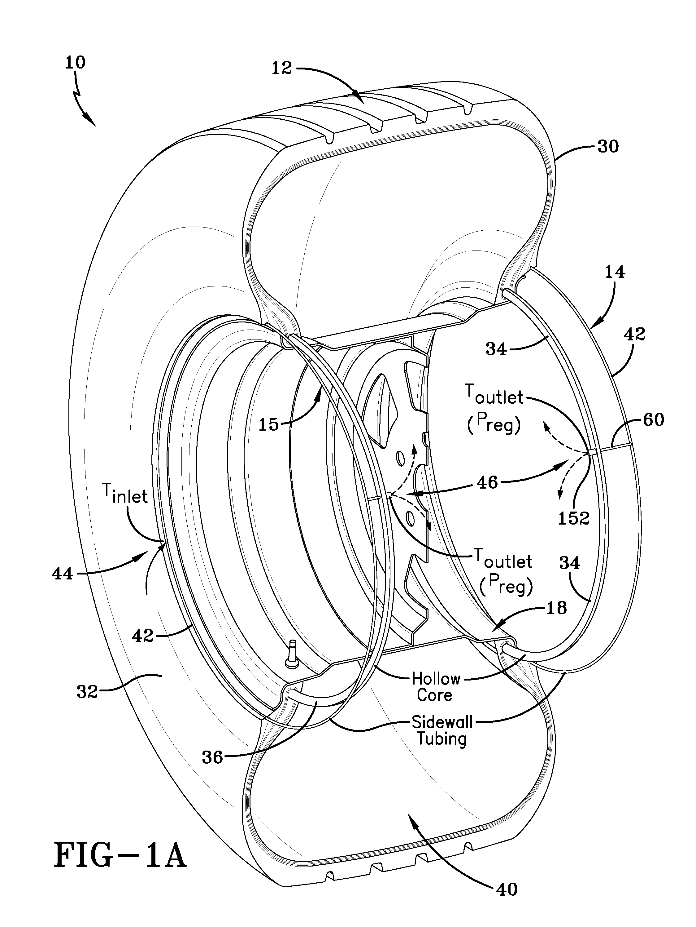
[0041]Referring to FIGS. 1, 1A, 2, and 6, a tire assembly 10 includes a tire 12, a pair of peristaltic pump assemblies 14, 15 and a tire rim 16. The tire mounts in conventional fashion to a pair of rim mounting surfaces 18, 20 adjacent outer rim flanges 22, 24. The rim flanges 22, 24, each have a radially outward facing surface 26. A rim body 28 supports the tire assembly as shown. The tire is of conventional construction, having a pair of sidewalls 30, 32 extending from opposite annular bead cores 34, 36 to a crown or tire tread region 38. The tire and rim enclose a tire cavity 40.

[0042]As seen from FIGS. 1, 1A, 2 and 3A, B, and C, each peristaltic pump assembly 14, includes an annular air tube 42 that encloses an annular passageway 43. While two pump assemblies 14, 15 are shown, one for each sidewall, it will be appreciated that a single pump assembly may be deployed without departing from the invention. For the simplicity of explanation, only the assembly 14 will be described in ...


PUM


Abstract

A self-inflating tire assembly includes a tire having a tire cavity between first and second sidewalls that extend respectively from first and second tire core beads to a tire tread region. At least one of the sidewalls is provided with an air tube peristaltic pump assembly. An air tube has an internal tube air passageway and is positioned within a sidewall groove in contacting engagement with opposite groove surfaces surrounding the air tube. The sidewall groove operatively bends within a rolling tire footprint to compress the air tube from an expanded diameter to a flat diameter adjacent the rolling tire footprint. A core bead passageway extends within a core bead adjacent the one tire sidewall for operatively storing air evacuated from the air tube passageway. Conduits are provided to route air from the air tube to the core bead passageway and valve mechanisms are positioned within the core bead passageway to control the flow of air from the core bead passageway into the tire cavity.

Description

FIELD OF THE INVENTION[0001]The invention relates generally to self-inflating tires and, more specifically, to a tire assembly incorporating a pump mechanism.BACKGROUND OF THE INVENTION[0002]Normal air diffusion reduces tire pressure over time. The natural state of tires is under inflated. Accordingly, drivers must repeatedly act to maintain tire pressures or they will see reduced fuel economy, tire life and reduced vehicle braking and handling performance. Tire Pressure Monitoring Systems have been proposed to warn drivers when tire pressure is significantly low. Such systems, however, remain dependant upon the driver taking remedial action when warned to re-inflate a tire to recommended pressure. It is a desirable, therefore, to incorporate a self-inflating feature within a tire that will self-inflate the tire in order to compensate for any reduction in tire pressure over time without a need for driver intervention.SUMMARY OF THE INVENTION[0003]According to an aspect of the invent...

Claims


Application Information

Patent Timeline
Patent Type & Authority Applications(United States)
IPC IPC(8): B60C5/22
CPCB60C23/12Y10T152/10495Y10T152/10594B60C23/123B60C23/135
Inventor LOSEY, ROBERT ALLEN
Owner THE GOODYEAR TIRE & RUBBER CO
Why Eureka
Try Eureka